Owner's Manual WARNING Exercise can present a health risk. Consult a physician before beginning any exercise program with this equipment. If you feel faint or dizzy, immediately discontinue use of this equipment. Serious bodily injury can occur if this equipment is not assembled and used correctly. Serious bodily injury can also occur if all instructions are not followed. Keep others and pets away from equipment when in use. Always make sure all bolts and nuts are tightened prior to each use.
TABLE OF CONTENTS Page Safety Precautions Before You Begin Hardware Illustrations Assembly Instructions Set Up Instructions Operational Instructions Storage Maintenance Page 2 4 5 6 10 11 14 14 Adjustment Instructions Conditioning Guidelines Warm-up and Cool-Down Warranty Product Parts Drawing Parts List Fax/Mail Ordering Form 15 17 18 19 20 21 23 SAFETY PRECAUTIONS WARNING: To reduce the risk of serious injury, read the following Safety Precautions before using the UX2 AIR BIKE. 1. 2. 3. 4. 5. 6. 7.
CALL US FIRST THANK YOU FOR PURCHASING THE STAMINA UX2 AIR BIKE To help you get started, we have pre-assembled most of your UX2 AIR BIKE at the factory with the exception of those few parts left unassembled for shipping purposes. Simply follow the few assembly instructions set forth in this manual. With regular workouts you will be getting your body into shape and on your way to achieving a happier and healthier lifestyle.
BEFORE YOU BEGIN Thank you for choosing the UX2 AIR BIKE. We take great pride in producing this quality product and hope it will provide many hours of quality exercise to make you feel better, look better and enjoy life to its fullest. Yes, it's a proven fact that a regular exercise program can improve your physical and mental health. Too often, our busy lifestyles limit our time and opportunity to exercise.
HARDWARE IDENTIFICATION CHART This chart is provided to help identify the hardware used in the assembly process. Place the washers, the end of the bolts, or screws on the circles to check for the correct diameter. Use the small scale to check the length of the bolts and screws. 3/16" 1/4" 5/16" 3/8" 1/2" INCHES 0 1/2 1 1/2 2 1/2 3 1/2 4 1/2 5 1/2 6 in. mm.
ASSEMBLY INSTRUCTIONS Place all parts from the box in a cleared area and position them on the floor in front of you. Remove all packing materials from your area and place them back into the box. Do not dispose of the packing materials until assembly is completed. Read each step carefully before beginning. If you are missing a part please call our toll-free number for assistance 1 (800) 375-7520 or e-mail us at: parts@staminaproducts.
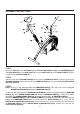
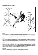
ASSEMBLY INSTRUCTIONS Strap STEP 4 Attach the SEAT(43) to the SEAT POST(4) with NYLOCK NUTS(M8x1.25)(62) and WASHERS(M8)(67). Slide BELLOWS(45) over the SEAT POST(4). Insert the SEAT POST(4) into the MAIN FRAME(1) and lock in position with LOCKING KNOB(46). STEP 5 Slide the Cable of the TENSION KNOB(27) into the slot on the MONITOR POST(5). Hook the top end of the TENSION KNOB(27) into the square hole on the MONITOR POST(5) and secure with FLAT HEAD SCREW (M5x0.8x15mm)(58).
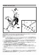
ASSEMBLY INSTRUCTIONS L R L R STEP 7 There is a "R" decal on the RIGHT HANDLEBAR(7) and RIGHT LINKAGE(74). Refer to above illustration. Press a LINKAGE BUSHING(42) into the RIGHT LINKAGE(74). Attach the RIGHT LINKAGE(74) onto the bottom end of LOWER BAR(8) with HEX HEAD BOLT(M8x1,25x45mm)(61), WASHER (M8xø22mmx1.5mm)(68), ARC WASHER(M8)(71), and NYLOCK NUT(M8x1.25)(62). STEP 8 Attach the right LOWER BAR ASSEMBLY(8) to the RIGHT HANDLEBAR(7) with ROUND HEAD BOLTS (M6x1x12mm)(59) and ARC WASHERS(M6)(70).
ASSEMBLY INSTRUCTIONS IMPORTANT STUDY THE ABOVE ILLUSTRATION AND READ ALL OF STEP 11 "a" through "g" BEFORE ATTACHING PEDALS AND CONNECTING LINKAGES. STEP 11 NOTE: The RIGHT PEDAL(32) has R marked on the bottom side of the pedal. The LEFT PEDAL(31) has L marked on the bottom side of the pedal. Both PEDALS(31, 32) have RIGHTHAND THREADS. Tighten both PEDALS(31, 32) by turning clockwise. a. Push PEDAL BUSHINGS(33), with SHOULDER facing outside, into LINKAGE CONNECTORS(75). b.
SET UP INSTRUCTIONS Place the UX2 AIR BIKE in the area where it will be used. It is recommended that the UX2 AIR BIKE be placed on an equipment mat. The UX2 AIR BIKE is approximately 42 1/2" long x 22 1/4" wide x 45 1/4" tall. (These dimensions may vary up to one inch.) An area 4 feet wide x 6 feet long is required for safe operation of the UX2 AIR BIKE. Make sure that adequate space is available for access to and passage around the UX2 AIR BIKE.
OPERATIONAL INSTRUCTIONS USING THE MONITOR POWER ON : Pedal movement or push the MODE button. POWER OFF : Automatic shut off after four minutes of inactivity. MODE BUTTON: Press to select display functions, include SCAN, TIME, SPEED, DISTANCE, and CALORIES. Press and hold for three seconds to reset all functions to zero. FUNCTIONS: SCAN: Automatically scans each function of TIME, SPEED, DISTANCE, and CALORIES in sequence with change every four seconds.
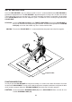
OPERATIONAL INSTRUCTIONS SEAT HEIGHT ADJUSTMENT Proper seat height is important for efficient exercise. To determine proper seat height, sit on the bike and center the ball of your foot on the pedal in the down position. Your leg should be slightly bent and relaxed as shown. If your leg is too straight or your foot cannot touch the pedal, you will need to lower the seat. If your leg is bent too much you will need to raise the seat. Remove the LOCKING KNOB(46).
OPERATIONAL INSTRUCTIONS Exercise Workout The secret to aerobic training is achieving a selected heart rate and maintaining it. The UX2 AIR BIKE, with its air resistance system allows the user to easily attain the desired pulse rate. Since no two people or life styles are alike, the UX2 AIR BIKE has been designed to allow the user to isolate portions of the body that may need greater emphasis in training.
STORAGE 1. 2. 3. 4. To store the UX2 AIR BIKE simply keep it in a clean dry place. The UX2 AIR BIKE is 42 1/2" long x 22 1/4" wide x 45 1/4" tall. The UX2 AIR BIKE must be lifted for movement. Two people may be required. To avoid damage to the electronics, remove the batteries before storing the UX2 AIR BIKE for one year or more. MAINTENANCE The safety and integrity designed into the UX2 AIR BIKE can only be maintained when the UX2 AIR BIKE is regularly examined for damage and wear.
ADJUSTMENT INSTRUCTIONS Chain Adjustment Chain Adjustment required if the Chain is too loose. 1. Loosen the NUTS(3/8"-26)(66) on both sides of the fan. 2. Adjust the NUT(M6x1)(65) on the chain side of bike to remove all slack from the chain. 3. Adjust the NUT(M6x1)(65) on the side opposite the chain so that the center of the NUT(3/8"-26)(66) is the same distance from TAB on both sides of bike. 4. Tighten the NUTS(3/8"-26)(66) on both sides of the fan.
ADJUSTMENT INSTRUCTIONS STEP 6: Hold the FAN(18) so that the FRONT SPROCKET is on your left side as shown. STEP 7: Loosen NUTS "A" and "B" until at least 1/2" of FAN AXLE is showing between NUT "A" and the FAN BUSHING. STEP 8: Tighten NUT "C" completely until it bottoms out on the last FAN AXLE thread. STEP 9: Tighten NUT "A" completely against FAN BUSHING, then back off 1/4 turn or until the FAN AXLE has a very small amount of play side to side.
CONDITIONING GUIDELINES How you begin your exercise program depends on your physical condition. If you have been inactive for several years or are severely overweight, start slowly and increase your workout time gradually. Increase your workout intensity gradually, too, by monitoring your heart rate while you exercise. Remember to follow these essentials: Have your doctor review your training and diet programs.
WARM-UP and COOL-DOWN Warm-up The purpose of warming up is to prepare your body for exercise and to minimize injuries. Warm up for two to five minutes before strength-training or aerobic exercising. Perform activities that raise your heart rate and warm the working muscles.
LIMITED WARRANTY MODEL 15-0960 WARRANTY Stamina Products, Inc. warrants that this product will be free from defects in materials and workmanship under normal use, service and proper operation for a period of 90 days on the parts and one year on the frame from the date of the original purchase from an authorized retailer.
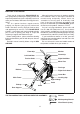
BACK PRODUCT PARTS DRAWING FRONT
PARTS LIST DIAGRAM# 1 2 3 4 5 6 7 8 9 10 11 12 13 14 15 16 17 18 19 20 21 22 23 24 25 26 27 28 29 30 31 32 33 34 35 36 37 38 39 40 41 42 43 44 45 46 47 PART NAME Main Frame Rear Support Front Stabilizer Seat Post Meter Post Left Handlebar Right Handlebar Lower Bar Left Linkage Crank and Sprocket Wavy Washer Small Keyed Washer Split Bearing Crank Bearing Retainer Large Keyed Washer Roll Pin Chain (1/4" pitch) Fan Resistance Hub Fan Bushing Fan Axle Eye Bolt (M6 x 1 x 55mm) Speed Pickup Tension Spring Tensio
PARTS LIST DIAGRAM# 48 49 50 51 52 53 54 55 56 57 58 59 60 61 62 63 64 65 66 67 68 69 70 71 72 73 74 75 76 77 78 79 80 81 PART NAME Leveling Cap (28.6mm) Endcap (45mm) Round Plug (25mm) Carriage Bolt (M8 x 1.25 x 38mm) Screw, Round Head (M4 x 15mm) Screw, Round Head (M5 x 15mm) Screw, Round Head (M5 x 15mm) Screw, Round Head (M5 x 25mm) Screw, Round Head (M5 x 75mm) Screw, Round Head (M5 x 0.8 x 12mm) Screw, Flat Head (M5 x 0.
FAX/MAIL ORDERING FORM Please do not return the product. For your convenience, Stamina has a Customer Service Department with a toll-free number. Should a part be missing or a defective part found, please call 1 (800) 375-7520 (in the U.S.) from 7:30 A.M. to 5:00 P.M. Central Time, Monday through Thursday and 8:00 A.M. to 3:00 P.M. on Friday or fill out the fax sheet ordering form below and fax it to (417) 889-8064.