
User's Manual


ASSEMBLY INSTRUCTIONS
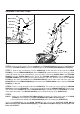
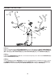
STEP 7: Refer to the inset drawing. Lay the UPRIGHT(6) on the floor close to the front of the MAIN
FRAME(1). Turn the TENSION KNOB(21) on the UPRIGHT(6) counterclockwise as far as it can go, so the
cable end extends out of the metal fitting as far as possible. Connect the CABLE END of the TENSION
KNOB(21) into the SPRING HOOK on the end of the TENSION CABLE(20). Pull the CABLE on the
TENSION KNOB(21) firmly and insert the cable through the slot in the bracket. Then insert the METAL
FITTING on the end of the CABLE of the TENSION KNOB(21) into the hole at the end of the slot in the
BRACKET. Adjust the TENSION KNOB(21) and verify that the SPRING HOOK moves when the TENSION
KNOB(21) is adjusted.
Bracket
Cable End
Spring Hook
Metal Fitting
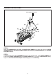
STEP 8: There is a strap attached inside of the UPRIGHT(6). This strap is to assist in pulling the SENSOR
WIRE(23) through the UPRIGHT(6). Tie the strap to the plug end of the SENSOR WIRE(23). Pull the strap
from the top of the UPRIGHT(6) until the SENSOR WIRE(23) is pulled through the UPRIGHT(6) as shown
in the above illustration. The SENSOR WIRE(23) must extend out the top of the UPRIGHT(6).
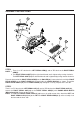
Make sure the NYLOCK NUTS(M8x1.25)(62) fit into the hex holes on the top of the MAIN
FRAME(1) before tightening the BUTTON HEAD BOLTS(M8x1.25x57mm)(49).
Be careful not to damage the SENSOR WIRE(23) when assembling the UPRIGHT(6).
1.
2.
STEP 9
NOTE:
Strap
Strap
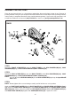
STEP 6: Refer to the illustration. Slide the CABLE on the TENSION KNOB(21) through the UPRIGHT(6).
Attach the TENSION KNOB(21) onto the UPRIGHT(6) with
FLAT HEAD SCREW(M5x0.8x15mm)(59).
8
Insert the UPRIGHT(6) into the MAIN FRAME(1) and secure with BUTTON HEAD BOLTS
(M8x1.25x57mm)(49), ARC WASHERS(M8)(66), and NYLOCK NUTS(M8x1.25)(62). Do not tighten the
bolts until STEP 10.