FF520 50/200kHz BLACK BOX FISH FINDER Owner's Manual
Congratulations on you purchase of the FF520! The STANDARD HORIZON organization is committed to ensuring your enjoyment of this unit. STANDARD HORIZON technical support personnel stand behind every product we sell, and our Product Support team invites you to contact us should you require technical advice or assistance, at 800/767-2450. FCC Compliance Statement This device complies with Part 15 of the FCC limits for Class A digital devices.
TABLE OF CONTENTS 1. INTRODUCTION ........................................................................................................ 7 1.0 GENERAL INFORMATION ............................................................................... 7 1.1 PACKING LIST ................................................................................................. 8 1.1.0 FF520 Packing List .............................................................................. 8 2. MOUNTING THE FF520 ....................
. FISH FINDER SETUP MENU .................................................................................... 25 4.0 PRESETS ...................................................................................................... 25 4.1 PAGE SELECTION ......................................................................................... 25 4.2 GAIN MODE .................................................................................................... 26 4.3 RANGE MENU ..................................
1. INTRODUCTION This chapter provides basic information in becoming familiar with the advanced functions of the FF520 before you start using it combined with the STANDARD HORIZON GPS Chart Plotters. 1.0 GENERAL INFORMATION The STANDARD HORIZON GPS Chart Plotters combined with the sonar performance of the FF520 creates the most advanced marine navigation system available. This Owner's Manual covers the Fish Finder functions of the FF520 when used with the STANDARD HORIZON GPS Chart Plotters.
Performance of the FF520 used in conjunction with optional transducers (sold separately) will vary based on water conditions, bottom composition, boat hull, vessel speed, installation, and specific transducer model. This includes but is not limited to both minimum and maximum depth performance. 1.1 PACKING LIST When the package containing the FF520 is first opened, please check for the following contents. 1.1.
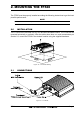
2. MOUNTING THE FF520 The FF520 must be properly installed according the following instructions to get the best possible performance. NOTE TRANSDUCER: refer to Chapter 6 and to the Installation Manual supplied with the transducer. 2.0 INSTALLATION The FF520 must be mounted in a dry, cool and well ventilated location. The FF520 can be mounted horizontally or vertically. After the cables have been run, and connected as per Section 2.2, mount the FF520 in the desired location using the supplied hardware.
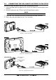
2.2 CONNECTING THE GPS CHART PLOTTERS TO THE FF520 CP155C/CP1000C/CP180/CP180i/CPV350 connections to FF520 1. If the power/data cable is plugged into the CP155C/CP1000C/CP180/CP180i/CPV350, remove it. 2. Route the cable from the FF520 to the GPS Chart Plotters location. NOTE You can disconnect the "Tee" cable from the FF520 to make installation easier. Refer to Section 7. 3. Plug in the "Tee" connector into the GPS Chart Plotter DC/Data connector. 4. Plug in the power data cable into the "Tee" connector.
CPV350 FF520 Tee Cable Figure 2.2c - CPV350 Connection CP175C connections to FF520 1. Cut off the "Tee" connector on the FF520 as close to the "Tee connector as possible. 2. Route the cable from the FF520 to the CP175C location. 3. Strip back the black insulation on the "Tee" cable about three inches to expose the wires inside the cable. Connect the wires from the CP175C to the FF520 "Tee" cable referring to Figure 2.2d CP175C Connection. Figure 2.2d - CP175C Connection 2.
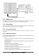
Figure 2.3a - The FF520 Optional Connections (II) 2.3.0 NMEA Output The following sentences are outputted: DPT and DBT (Depth), VHW (Speed), VLW (Trip Log), MTW (Water Temperature), XDR (External Sensor Temperature). 2.3.1 Alarm Buzzer This connection has the capability to drive a buzzer that draws 400mA. Any 12VDC buzzer within the current draw requirements can to be connected. 2.3.2 Second temp sensor Any thermistor type temp sensor that produces 10K ohms at 77 degrees F can to be connected. 2.
· 3 SHORT FLASHES EVERY 2 SECONDS A non-Standard Horizon transducer (without transducer ID) has been connected · 4 SHORT FLASHES EVERY 2 SECONDS No transducer connected. 2.4 POWER CONNECTIONS It is recommended the installation of a switch and a 5A fuse (not supplied) in the positive DC supply to the FF520. The FF520 is designed to remain in stand-by mode even when the power of the GPS Chart Plotter is turned off.
Figure 2.4.0 - Selecting the FF520 on CP180/CP180i/CPV350 CP155C/CP175C/CP1000C 1. 2. 3. 4. 5. 5. Press [MENU]. Select SETUP and press [ENTER]. Select ADVANCED SETUP and press [ENTER]. Select IN/OUT CONNECTIONS and press [ENTER]. Select Port 2 and press [ENTER], select FF520 and press [ENTER]. Press [CLEAR] 3 times to exit. Figure 2.4.
3. FISH FINDER This chapter is intended to help you understand how STANDARD HORIZON GPS Chart Plotters with the FF520 connected operate. The FF520 consists of a high power transmitter, sensitive receiver and a transducer. The FF520 sends an electrical pulse to the transducer which contains a element that converts the pulse into acoustic (sound) wave which is sent through the water.
1 Warning message 2 Fish Finder window 3 Color Bar 6 4 Digital Depth 7 5 Water temperature 1 6 Alarm Bar 2 7 Depth ruler 8 Variable Depth Marker (VDM) 9 Zoom Bar 10 A-Scope 11 Operating Frequency 3 4 5 8 9 10 6 11 Figure 3.0 - The Fish Finder page Following there is a brief description of terms listed in the previous Figure 3.0: Warning Message This is a flashing label that is turned on when the echo sounder is in Simulation mode.
Variable Depth Marker (VDM) Horizontal line on to the Fish finder page window with a depth label. Move the ShuttlePoint knob Up or Down to change the position of the VDM. The label displays the depth of the cursor position. The VDM can be moved to any location pinpointing the depth of a target. Zoom Bar Range bar that is located on the left side of the Depth Ruler representing the current zoom range.
fishing since often many species of game fish like to suspend in, just above, or just below the thermoclines. White Line The White Line shows the difference between hard, soft bottoms and even distinguishes between fishes and structures located near the bottom. In this way it is easier to tell the difference between a hard and soft bottom and even to distinguish fishes and structures located nearby the bottom.
3. Press [ENTER] to select the Fish Finder Setup menu. 3.1.0a Menu selection for CP180/CP180i/CPV350 1. From all pages except the Fish Finder page, press [MENU]. 2. Move the ShuttlePoint knob to highlight FISH FINDER. Figure 3.1.0a - Example of Fish Finder page selection by [MENU] on CP180/CP180i 3. Press [ENT] to select the Fish Finder Setup menu. 3.1.
Figure 3.1.2 - Example of Fish Finder page selection by Soft Keys on CP1000C 3.1.3 Customizing the Soft Keys for CP175C/CP1000C/CPV350 All of the Soft Keys may be customized to select the three Fish Finder display to be able to quickly select each mode: 200kHz 50kHz 50/200kHz Figure 3.1.3 - Fish Finder FULL DISPLAY pages To customize a Soft Key : 1. Press any of the Soft Keys. 2. Press and hold one of the Soft Keys until the menu is shown below. ACQUIRING Figure 3.1.
3.2.0 The MENU key 1. Pressing [MENU] when a Fish Finder page is displayed, will show the Fish Finder Setup: Figure 3.2.0 - The MENU key, Fish Finder Setup 2. If pressed again the GPS Chart Plotters Main Menu will be displayed. NOTE To change to the Chart page [MENU] must be pressed 2 times to show the Main Menu. Then move the ShuttlePoint Knob to select the Chart page and press [ENTER] or move the ShuttlePoint knob to select the Chart page. 3.2.1 The ENTER key 1.
Move the ShuttlePoint knob up or down to move the VDM to the area you wish to zoom into. Press [ZOOM IN] once, and 2X will be shown in the bottom left corner of the display. Pressing [ZOOM IN] again switches to 4X and again to normal operation. Pressing [ZOOM OUT] switches from 4X to 2X and normal. 3.2.4 The MARK key With the Fish Finder page is displayed, pressing [MARK] places a Mark on the chart page under the boat position. 3.2.
The RANGE Soft Key By pressing [RANGE] the window switches to the next RANGE status: MANUAL, BOTTOM LOCK and AUTO. If MANUAL is selected move the ShuttlePoint knob up or down will adjust the depth value in 10 Ft steps. To adjust the Shift move the ShuttlePoint knob to the Left or Right. When BOTTOM LOCK is selected, move the ShuttlePoint knob up or down to adjust the Bottom range 10 Ft at a time. If AUTO RANGE, the range value is set automatically by the FF520 and it cannot be changed by the user.
7. Move the ShuttlePoint knob to highlight YES and press [ENTER] to confirm. 8. Press [CLEAR] to exit. WARNING Turn Off and after few seconds turn On the Fish Finder in case of failed firmware upload. 3.4 SYSTEM INFORMATION PAGE FOR CP180/CP180i/CPV350 For troubleshooting you maybe asked by a Standard Horizon Product Support Technician for the software version of Fish Finder. The following procedure is how to access this information. 1.
4. FISH FINDER SETUP MENU · From the Full Fish Finder page, press [MENU] to show the Fish Finder Setup menu. Figure 4 - Fish Finder Setup menu · From the Chart page, to access this menu: 1. Press [MENU], move the ShuttlePoint knob to SETUP and press [ENTER]. 2. Move the ShuttlePoint knob to FISH FINDER SETUP and press [ENTER]. The following paragraphs describe the Fish Finder Setup menu sub-options. 4.0 PRESETS Allows selection of the following preset modes: FISH, CRUISE.
Figure 4.1 - Page Selection sub-menu The Page Selection options are: Auto Full Display Chart/Fish Zoom Full page 4.2 : Selects automatically the 50kHz if depth is greater than 400 ft and selects 200kHz if depth is less than 300 ft : Shows the full Fish Finder page allowing to select among the 200kHz Standard Fish Finder, 50 kHz Standard Fish Finder or 200/50 kHz Dual Fish Finder. : Shows the Chart page on the left half of the screen and the Fish Finder on the right half of the screen.
automatically tracks the range around the bottom specified by the Bottom Range value. : Moves the display from showing the bottom to the depth value entered. : Shifts the display from the bottom of the transducer to the depth value entered. Depth Shift Example Your vessel is in about 57FT of water, however there is fish suspended in 35FT of water. You want to display to 10FT area around the fish. Shift would be set to 25FT and Depth would be set to 35FT shown in example below. Figure 4.
STC STC Length STC Strength Surface Noise Filter (**) : Sensitivity Time Constant: it is a time varying gain curve which attenuates the sonar receiver gain in shallow water, increasing the gain gradually as the depth increases. This is for the purpose of filtering out surface clutter. : If STC is Custom, it is possible to change the Length of the Sensitivity Time Constant. : If STC is Custom, it is possible to change the Strength of the Sensitivity Time Constant.
The following are examples of Color Settings: Figure 4.6a - Color Settings item Figure 4.6b - Examples of Color Settings: white on the left and blue on the right 4.7 TRANSDUCER SETUP This menu allows you to calibrate the speed through the water, water temperature and the keel/prop offset of the transducer. Figure 4.
Calibrate Water Speed : Calibrate Water Temp : Calibrate Aux Temp : Set Default : 4.8 we would enter an offset of +5 feet. Then in this example, the digital depth would report a depth of 20 feet (from the surface) and the graphic image scale range would shift from 0 to 20' to 5 to 25'. Allows calibrating the value of Water Speed coming from the transducer. The calibration value, in the range between -10% to +10%, will be applied to the water speed from the transducer.
4.11 RESTORE CURRENT PRESET DEFAULTS This option restores the default values only for the current presets (see Par. 4.0, Preset) and does not affect the other presets.
Page 32 FF520
5. SPECIFICATIONS 5.0 FF520 SPECIFICATIONS Power supply Max stand by current draw : : : Max current draw : : Sounder Power : Display Colors : Display Vertical Resolution : : Frequency : Max Depth* : : Min Depth : Max Typical* : : 10 - 35 Volt dc 1KW:142mA at 12 Volt dc 500W:100mA at 12 Volt dc 1KW:1.
based on water conditions, bottom composition, boat hull, vessel speed, installation, and specific transducer model. This includes but is not limited to both minimum and maximum depth performance. 5.1 FF520 INTERNAL CONNECTIONS NOTE The image below is for your reference only. Since the FF520 is pre-wired it is recommended that the box not be disassembled. Figure 5.
6. TRANSDUCER The transducer is a device that transmits and receives sound waves into the water. The active component inside the transducer is commonly referred to as an element but actually is a piezoelectric ceramic material. 6.0 6.0.0 TRANSDUCER MOUNTING Power Boats Basically there are 2 hull types of powerboats Planing and Displacement. In the pictures shown below the boxes with lines are where the transducer should be installed. Figure 6.0.
Figure 6.0.1a - Full Keel Figure 6.0.1b - Mounting Area 6.0.2 Transducer Types Since there are many different shapes and sizes of hulls, STANDARD HORIZON offers a range of Depth transducers to fit the vessels requirements. 6.0.3 Low Profile Thru-Hull If the user is planning to mount a thru-hull transducer first he has to know the dead rise angle where the transducer will be located on the boat.
6.0.6 In-hull This transducer is epoxyed to the inside of the hull that is not more than 1/2 inch thick and is solid not cored. 6.1 OPTIONAL TRANSDUCER ID SENSORS Figure 6.
Page 38 FF520
7. TIPS OF OPERATIONS 7.0 HOW CAN I DISCONNECT THE CABLES FROM THE FF520 IN CASE I NEED TO DO SO FOR THE INSTALLATION? · Open the FF520 box by unscrewing the four screws (see the following figure). Figure 7.0 - The FF520 (I) · Once the screws are removed, pull out the panel and the Printed Circuit Board (PCB). Unscrew the cables from the PCB. Figure 7.0a - The FF520 (II) · Wire the cables as needed. · Reconnect the cables to the PCB (see the Figure 5.1 for reference).
Figure 7.0b - The FF520 (III) 7.1 HOW CAN I SET OPTIMAL OPERATING PARAMETERS. Optimal operating parameters can be set accordingly with the intended use of the Fish Finder, to quickly get optimal operational parameters for fishing it is may be best to select the FISH preset from the Fish Finder Setup menu, while for cruising it is may be best to select the CRUISE preset. 7.2 WHAT ARE PRESET MODES? Preset modes are pre-defined settings of the Fish Finder operating parameters.
when the water is full of materials in suspension, with bad sea conditions. 7.6 WHAT SHOULD I DO IF THE AUTO MODES FAIL? Failure of auto modes can happen for various reasons. Hereafter you can find a range of possibilities. 7.7 AUTO-RANGE FAILS IN VERY SHALLOW WATERS DISPLAYING A DIGITAL DEPTH READOUT DEEPER THAN THE ACTUAL VALUE.
surface clutter, and increasing the STC strenght until the image on the screen cleans up. Please note that in very shallow waters it is usually better to switch to manual gain mode to reduce gain fluctuation due to rapidly changing bottom conditions. 2) Using Surface Declutter, increase the Surface Declutter value until the surface declutter disappears completely. 7.11 WHY DO I NEVER SEE FISHES IN THE RANGE BETWEEN 0 TO 2 FEET? The minimum range of the Fish Finder is 2 Feet.
INDEX A A-Scope .......................................................... 17 Alarm Bar ........................................................ 16 Alarms ............................................................. 30 B Bottom Echo Profile ........................................ 18 C Calibrate Aux Temp ......................................... 30 Calibrate Water Speed .................................... 30 Calibrate Water Temp ..................................... 30 Chart/Fish .........................
STANDARD HORIZON LIMITED WARRANTY STANDARD HORIZON (a division of Vertex Standard USA) warrants, to the original purchaser only, each new Marine Product ("Product") manufactured and/or supplied by STANDARD HORIZON against defects in materials and workmanship under normal use and service for a period of 3 years from the date of purchase.