IP16 HYDRAULIC INTENSIFIER USER MANUAL Safety, Operation and Maintenance © 2014 Stanley Black & Decker, Inc. New Britain, CT 06053 U.S.A. 10413 9/2014 Ver.
TABLE OF CONTENTS SAFETY SYMBOLS...................................................................................................................................................4 SAFETY PRECAUTIONS...........................................................................................................................................5 TOOL STICKERS & TAGS.........................................................................................................................................6 HOSE TYPES...
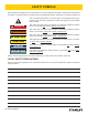
SAFETY SYMBOLS Safety symbols and signal words, as shown below, are used to emphasize all operator, maintenance and repair actions which, if not strictly followed, could result in a life-threatening situation, bodily injury or damage to equipment. This is the safety alert symbol. It is used to alert you to potential personal injury hazards. Obey all safety messages that follow this symbol to avoid possible injury or death.
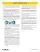
SAFETY PRECAUTIONS Tool operators and maintenance personnel must always comply with the safety precautions given in this manual and on the stickers and tags attached to the tool and hose. These safety precautions are given for your safety. Review them carefully before operating the tool and before performing general maintenance or repairs. Supervising personnel should develop additional precautions relating to the specific work area and local safety regulations.
TOOL STICKERS & TAGS DANGER Failure to use hydraulic hose labeled and certified as non-conductive when using hydraulic tools on or near electric lines may result in death or serious injury. For proper and safe operation read owners manual and mwke sure that you have been properly ELECTROCUTION HAZARD trained in correct procedures required for work on or around electric lines.
HOSE TYPES The rated working pressure of the hydraulic hose must be equal to or higher than the relief valve setting on the hydraulic system. There are three types of hydraulic hose that meet this requirement and are authorized for use with Stanley Hydraulic Tools. They are: Certified non-conductive — constructed of thermoplastic or synthetic rubber inner tube, synthetic fiber braid reinforcement, and weather resistant thermoplastic or synthetic rubber cover.
► IP16 User Manual All hydraulic hose must meet or exceed specifications as set forth by SAE J517. All hydraulic hose must have at least a rated minimum working pressure equal to the maximum hydraulic system relief valve setting. This chart is intended to be used for hydraulic tool applications only based on Stanley Hydraulic Tools tool operating requirements and should not be used for any other applications.
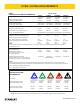
HTMA / EHTMA REQUIREMENTS HTMA / EHTMA REQUIREMENTS HTMA HYDRAULIC SYSTEM REQUIREMENTS TYPE I Nominal Operating Pressure (at the power supply outlet) 4-6 gpm (15-23 lpm) 1500 psi (103 bar) TOOL TYPE TYPE II TYPE RR 7-9 gpm (26-34 lpm) 1500 psi (103 bar) 9-10.
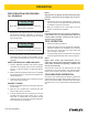
OPERATION PRE-OPERATION PROCEDURES FILL RESERVOIR IMPORTANT Mil-H 5606 Hydraulic Oil must not be used in the reservoir of the intensifier. 1. Remove the vent plug from the top of the intensifier. Fill with clean hydraulic oil filtered to 10 microns or less. Fill to top of high pressure pump as viewed from the filler hole. IMPORTANT Do not fill to top of hole. An air space is required for hydraulic oil expansion as oil temperature increases. 2.
TOOL PROTECTION & CARE NOTICE In addition to the Safety Precautions found in this manual, observe the following for equipment protection and care. • Make sure all couplers are wiped clean before connection. • The hydraulic circuit control valve must be in the OFF position when coupling or uncoupling hydraulic tools. Failure to do so may result in damage to the quick couplers and cause overheating of the hydraulic system. • Always store the tool in a clean dry space, safe from damage or pilferage.
TROUBLESHOOTING If symptoms of poor performance develop, the following chart can be used as a guide to correct the problem. When diagnosing faults in operation of the intensifier, always check that the hydraulic power source is supplying the correct hydraulic flow and pressure to the intensifier as listed in the table. Use a flow meter known to be accurate. Check the flow with the hydraulic fluid temperature at least 80 °F/27 °C. PROBLEM No output. Oil mist from center of motor housing assembly.
SPECIFICATIONS Output Pressure.............................................................................................................................10,000 psi/700 Bar Input Pressure......................................................................................................................... Up to 2500 psi/176 Bar Flow Range................................................................................................................................ 4–10 gpm/15–38 lpm Porting..............
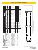
IP16 PARTS ILLUSTRATION 14 ► IP16 User Manual
IP16 PARTS LIST PART NO. QTY DESCRIPTION ITEM PART NO.
Stanley Hydraulic Tools 3810 SE Naef Road Milwaukie, Oregon 97267-5698 USA (503) 659-5660 / Fax (503) 652-1780 www.stanleyhydraulics.