
Owner's Manual
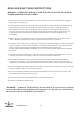


WARNING: blades should be at least 7 feet from floor
O
F
F
O
F
F
O
F
F
Turn off power at breaker box to avoid possible
electrical shock.
Use metal outlet box suitable for fan support.
Outlet box must support 35 lbs min.
Note 1: Note 2:
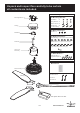
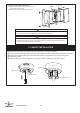
1. HANGING SYSTEM INSTALLATION
1A.Installing mounting bracket to ceiling outlet box
2 Screw (2)
(Loosening)
1 Outlet Box
Mounting
Bracket
1 Install mounting bracket to outlet box in ceiling by
using screws included with the outlet box and washers
from the hardware bag.
2 Loosen the bottom screws from Mounting Bracket.
Do not remove.
Yoke
Downrod
Assembly
Fan
Assembly
Deco Ring
Wire Connectors
from Yoke Cover
Assembly
Cross Pin
Cotter Pin
Jam Screw
with Hex Nut(1)
(Tightening)
Wire Connectors
from Fan
Jam Screw
with Hex Nut(1)
(Loosening)
Canopy
Yoke Cover
Assembly
Cross Pin
Cotter Pin
Canopy
Yoke cover
Downrod
Deco Ring
Canopy
Yoke Cover
Assembly
Wires
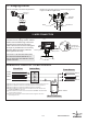
1B. Installing Downrod and Yoke
1
2
Insert downrod through Canopy, Deco Ring and Yoke Cover and feed motor lead wires through Downrod.
3
4
5
6
7
Fig.1
Fig.2 Fig.3
See Fig.1
Remove cross pin and cotter pin from downrod.
Loosen 1 Downrod jam screws at Yoke. Insert Downrod Assembly into Yoke.
Insert the cross pin through Yoke & Downrod and secure with cotter pin.
Tighten Downrod jam screws to further secure Downrod.
Attach Wire Connectors from Yoke Cover Assembly and from fan to tight.
Pull down the Yoke Cover Assembly.
See Fig.2
See Fig.3
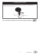
P3
Mounting
Bracket
Lift fan assembly onto Mounting Bracket.
Rotate fan to let the groove on the ball engages the
ridge in the Mounting Bracket.
1C. Hanging the fan
Ridge
Ball Groove
Mounting
Bracket
P4
2. WIRE CONNECTION
2A. Attaching safety cable to ceiling joist
Safety Cable
Safety
cable
Flat Washer
Spring Washer
Wood Screw
Outlet Box
Use wood screw, spring washer, and flat
washer from hardware bag. Pass wood
screw through closed loop of safety
cable. Secure wood screw to ceiling joist
through any available slot on mounting
bracket. Make sure safety cable has
beentightened securely.
CAUTION: THE WOOD SCREW AND
ITS SUPPORT MUST BE ABLE TO
FULLY SUPPORT THE WEIGHT OF AT
LEAST 100 LBS.
Canopy
Mounting Bracket
2B.Make wire connection - for Wall Controller
White
Green
( Motor - N )
( Motor - L )
Black
( from downrod )
Green
( AC - L )
( AC - N )
From Fan
From House
1 Connect two green wires from fan and green wire from house by wire nut.
2 Connect white wire from fan and white wire from house by wire nut.
3 Connect black wire from fan and black wire from outlet box.
4 Connect black wire from outlet box and black wire from wall control
marked ”To FAN” by wire nut.
5 Connect black wire from wall control marked ”To HOT” and black wire
from House by wire nut.
6 Connect green/yellow wire from wall control and green wire from
House by wire nut.
White
Black
TO HOT
TO FAN
Wall Controller
Outlet Box
1
2
3 4 5
( from mounting bracket )
Green
Green / Yellow
6
www.starfans.co