STAR TRAC FITNESS TM PERSONAL VIEWING SCREEN OWNER’S MANUAL
TABLE OF CONTENTS Introduction . . . . . . . . . . . . . . . . . . . . . . . . . . . . . . . . . . . . . . . . . . . . . . . . . . . . . . . . . . . . . . . . . . . . . . . . . . . . . . . . . . . . . . About This Manual . . . . . . . . . . . . . . . . . . . . . . . . . . . . . . . . . . . . . . . . . . . . . . . . . . . . . . . . . . . . . . . . . . . . . . . . . Before You Get Started . . . . . . . . . . . . . . . . . . . . . . . . . . . . . . . . . . . . . . . . . . . . . . . . . . . . . . . . . . . .
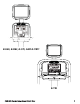
i PULSE TM E-UBi, E-RBi, E-STi, AND E-TBTi i PULSE TM E-TRi STAR TRAC PERSONAL VIEWING SCREEN OWNER’S GUIDE 3
INTRODUCTION Thank you for adding the STAR TRAC PERSONAL VIEWING SCREEN (PVS) to your Star Trac Purchase. The Personal Viewing Screen has been designed to provide the user with the most rewarding experience based upon the carefully planned features it possess. The design elements of this Personal Viewing Screen will provide you with a comfortable, intuitive, safe and reliable experience, guiding you to a habit-forming lifestyle.
BEFORE YOU GET STARTED CHECK FACILITIES PREPAREDNESS For a proper installation, please read this guide thoroughly and follow the instructions. Star Trac’s goal is to help you have a successful and reliable installation, for this reason we have come up with some helpful tips and check list to accomplish this goal. EQUIPMENT LAYOUT Check to see that the equipment you will be adding the PVS to are place where they will be used.
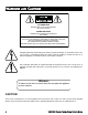
WARNINGS AND CAUTIONS ATTENTION RISQUE DE CHOC ELECTRIQUE, NE PAS OUVRIR PRECAUCION RIESGO DE CHOQUE ELECTRICO NO ABRIR CAUTION: TO REDUCE THE RISK OF ELECTRIC SHOCK, DO NOT REMOVE COVER ( OR BACK). NO USER-SERVICEABLE PARTS INSIDE. REFER SERVICING TO QUALIFIED SERVICE PERSONNEL.
This STAR TRAC Personal Viewing Screen has been engineered and manufactured to assure your safety. Before using this product, be sure to read your user’s manual in order to maximize the life of your display. DO NOT disassemble the PVS. Any Un-authorized maintenance will void the warrenty. Un-experienced technicians can cause serious damage, electric shock, and other hazards. Contact your dealer or an experienced technician for repair.
STAR TRAC PERSONAL VIEWING SCREEN (PVS) UNPACK YOUR PERSONAL VIEWING SCREEN Inspect the shipping carton for any parts that may be missing BEFORE discarding the carton. Items can shift during transportation, and may be accidentally discarded with the carton. If any parts are missing, please contact Star Trac Product Support at 800-503-1221. Have the serial number of the PVS, and a list of the missing parts ready so they may be shipped to you.
• Power Cord, Nema 6-15 (NOT INCLUDED IN THE E-TRi KIT) • Power Cord, Nema 5-15 (NOT INCLUDED IN THE E-TRi KIT) • Owners Manual PAL/SECAM Kit (Europe, Middle East) NOTE: there are 4 different kits ie. E-TRi, E-TBTi/E-UBi, E-RBi, AND E-STi.
INSTALLING YOUR PERSONAL VIEWING SCREEN (PVS) The Star Trac Personal Viewing Screen is different for each of your Star Trac E-Series Cardio products. Make sure you have the proper kit for the E-Series product you are installing. The E-UBi, E-RBi, E-TBTi, and the E-STi will follow the same basic steps for installation. For the E-TRi turn page 18 in this section.
After all the cable/harnessing has been disconnected, place the front display plastics aside for later use. Be careful with the display and place it face down on top of a non-scratching surface. You can use the foam bag that ships inside the Personal Viewing Screen package to place the display face onto. This will help protect it from being damaged. Screws STEP 4 Remove the cap cover with the Star Trac logo from the plastics by removing the (2) screws using a #2 Phillips screwdriver.
M8 Buttonhead STEP 7 Install the (4) M8 Buttonhead Screws through the PVS mounting bracket into the display mount. Note: (2) of the screws are in the PVS kit, (2) retained from step 5. Do not tighten them at this time. Screws STEP 8 Adjust the cap with the grommet into place. Using the 5mm Hex Key, tighten the M8 Buttonhead Screws to 190 lb-in (21.5 N-m) of torque. Take the (2) Phillips head screws you removed from the original cap and snugly tighten screws down using a #2 Phillips screwdriver.
STEP 10 Using a #2 Phillips head screwdriver, remove the screw that holds in the blank cover where the new Head Phone Jack mount will go. Next remove the blank cover. You will no longer need this item and it can be stored away for any possible future use. Retain screw for later use. Screw Blank cover STEP 11 Take the PVS center console from the kit. STEP 12 Insert the new center console into the front display.
With the changes now completed on the display, it is now time to re-install the display to the base unit. There are the (3) cables from the PVS mount that will need to be attached to the display. One cable from the PVS mount will be fed through the display which will be connected to the head phone jack later. The fifth cable from the PVS mount, which is the coax, will be connected to the coax on the base unit. There are (2) cables from the base unit that will be connected to the display.
STEP 16 Using a tie wrap from the PVS kit, bind the cables from the PVS neck to one side of the display mount. Take the tie and put it through the hole on one of the display mount tubes. Tie Wrap STEP 17 Now, take the front display plastics with the new Center Console to the base unit. Hold the front display plastics at the top with one hand while connecting the cables/harnesses with the other. There is no particular order in connecting the cables/harnessing.
STEP 19 Feed the Head Phone Jack cable from the PVS display neck through the hole in the front display plastics where the blank cover was removed earlier. STEP 20 Now that all the cables are in their places, and confined to the post on the display mount. Place the display front plastic onto the back. Make sure the bottom of the display front is under the 2 tabs on the display mount. Press the front display against the round tube and rotate it to the back. Be careful not to pinch any wires.
STEP 23 Now with the Personal Viewing Screen installed on your Star Trac equipment, it is time to connect your entertainment cable and power to the unit Look at the bottom of the neck, next to the floor. Connect your in-house Entertainment cable to the RF input. Take the power supply from the PVS kit and plug the small barrel connector to the DC input. Now take the appropriate Power Adapter Cable from the kit and plug it into the power supply and the electrical receptacle.
To install on the E-TR, follow these steps: STEP 1 Using a #2 Phillips screwdriver, remove the (8) screws from the upper back of the display. Place the cover somewhere safe to keep it from being damaged. Next, remove the (6) screws from the lower back of the display. Place the cover with the other one. Retain all the screws for later use. Screws Screws Screws Screws STEP 2 Now remove the upper cap cover that has the STAR TRAC logo on it. This cap is held in by the upper back cover.
Ribbon STEP 4 Detach the Center Console Ribbon Cable from the display board by gently pulling on the ribbon connector. Using a #2 Phillips screwdriver to remove the (4) screws that hold the center console in place. Retain the screws for later use. Remove the center console. You will no longer need this center console and, if desired, you can store it away for any possible future use. Screws Screws STEP 5 Take the Personal Viewing Screen from the PVS kit.
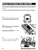
STEP 8 Now that the PVS is mounted to the Treadmill, you need to route the wires to their proper places. 2 4 Take the coax cable 1 and feed it all the way down the treadmill neck. Center Console Hole 2 Feed the DC power cable from the treadmill neck through the center console hole. Next take the Head Phone Jack cable 3 from the PVS neck and connect it to the Head Phone Jack. Now feed the other (3) cables 4 through the display and out the center console hole.
STEP 10 While holding the New Center Console near the opening of the display, connect the following cables to there approprate connector.(There is no particular order) 2 Plug in the (2) DC power cables to the DC connectors, (they are the same so it does not matter which goes to which). Plug in the PVS Remote Cable to the 3 PVS Remote Connector. Plug in the RCA Cable to the Video (6-pin) and the Audio (2-pin) connector, respectively , 6 RCA Connectors.
STEP 13 7 5 4 From below the display, connect the Center Console Ground Cable to 7 the Quick Disconnect Tab on the display mount. Connect the Keypad Tail to the 5 Keypad con- nector on the display PC board. Connect the Interface Cable to the 4 Interface connector on the display PC board. Screws STEP 14 Go to the base of the treadmill neck. Using a #2 Phillips screwdriver, remove the (2) screws that hold in the RF cable Mounting Bracket. Retain the screws for later use.
Screws Screws STEP 17 Replace the top back plastic. Using a #2 Phillips screwdriver insert the (8) screws, retained from earlier step, into the plastic. Do Not tighten at this time. STEP 18 Check the cap with the neck and grommet. Make sure the cap is flush with the top back plastic. Adjust if necessary. Use the screwdriver to tighten the screws snug from the previous step. Caution: Do Not over tighten screws. Flush This completes the installation of the Personal Viewing Screen on the E-TR treadmill.
SETTING UP YOUR PERSONAL VIEWING SCREEN Now that your Personal Viewing Screen is installed on your Star Trac Cardio Equipment, it is time to set it up. There are 2 types of Personal Viewing Screens, turn to the section that applies to your unit. NTSC / ATSC Personal Viewing Screen Set up E-UBi, E-RBi, E-STi, AND E-TBTi To enter the setup menu, you need to press pad, at the same time.
To navigate through the setup screens you will use the Entertainment Center Console keypad. To move between the items on the Main Menu, press the Sub Menu, press the or . While in the sub menu use the teen items, to select an item press the as applicable, then press the . Use the . To move to the items on the or and down to move bewto modify the selected item to return to the sub menu. Use the to return to the Main Menu.
TUNING BAND Air: Use this selection when a terrestrial(indoor/outdoor) antenna is used. Cable: Use this selection for standard analogue cable. Consult cable provider of cable type prior to set up. HRC: Harmonically related carriers. IRC: Incrementally related carriers. CABLE AUTO: Use to automatically sense the cable type. CABLE MODE When you set Tuning Band to CABLE, your menu selections will change. Cable mode will set the type of cable service you are using. Consult cable provider for cable type.
CHANNEL LABELS You can change the channel labels for each of the viewable channels. Analog channels are shown as ------ because there is no channel name info. Digital channels without channel info will also be displayed as ------. Some channels of digital broadcasting may be misnamed. Use the and to navigate between channels. Use the and to move to the next letter of the selected channel, or back to the channel selection area.
NTSC BRIGHTNESS: Adjust to brighten or darken the picture. SHARPNESS: Further you go left, more the screen softens, and further you go right, more the screen sharpens. Caution: When sharpness is too high, video noise soars in some videos which may cause problems in image quality. Normal setting is recommended. COLOR: Adjust to increase or decrease the Color intensity. TINT: Adjust color tone. COLOR TEMPERATURE: Default to NORMAL ASPECT RATIO: Image size on screen, Default to NORMAL.
NTSC TREBLE: Will adjust the treble tone for the sound output. BALANCE: Will adjust the sound volume between the right and left ear. DIGITAL AUDIO OUTPUT: Push the OK button, and it changes to PCM or RAW. SETTINGS: When you execute this menu, all Audio-related values which were previously set will reset to the factory default.
PAL / SECAM Personal Viewing Screen Set up Before you can set up the Personal Viewing Screen you must first get into the “Maintenance Mode” of the Star Trac Cardio Equipment, while is this mode you will tell the equipment what type of Personal Viewing Screen you are installing. For the “Maintenance Mode” on the E-TR follow the steps below; 1. Press and hold the Equipment. , , and keys together on the display keypad of the Cardio 2.
7. Press the to exit. This completes the E-TR setup, now turn to the “Accessing The On Screen Display” to continue. For “Maintenance Mode” on the E-TBT, E-ST, E-RB, and E-UB follow the steps below. 1. Press and hold the and keys together. , 2. A beep will sound and “MAINTENANCE SETTINGS” will display momentarily in the Information Window. 3. Release all keys. “SERIAL NUMBER” will display in the Information Window.
PAL/SECAM ACCESSING THE ON SCREEN DISPLAY (OSD) To enter the On Screen Display (OSD) setup menu, you need to press and hold the , and at the same time press the and , on the Entertainment Center Console keypad. The On Screen Display requires either a strong video signal or no video signal. If you are unable to get into the On Screen Display, try changing the channel, if that does not work, disconnect the RF cable at the base of the unit.
PAL/SECAM ADJUSTING THE ON SCREEN DISPLAY Picture Picture Mode Brightness Contrast Sharpness Saturation Tint C o l o r Te m p . Aspect Ratio Move User Normal Zoom MENU E x i t Select PICTURE MENU Use the and to navigate to the Picture menu. To enter the sub menu press to navigate to the desired sub menu. Use the modify. Once a sub menu element is selected use the you are finished with that item press the different element or press the .
PAL/SECAM SETTING THE SOUND Sound Sound Mode Bass Tr e b l e Balance MTS AV C Move Standard MONO Off Select MENU E x i t This menu is for adjusting the following items. Sound Mode: Default is Standard Bass: Will adjust the bass tone of the sound output. Treble: Will adjust the treble tone for the sound output. Balance: Will adjust the sound volume between the right and left ear. MTS: Multi Channel Television Sound. AVC: Auto Volume Control. Use the and to navigate to the Sound menu.
PAL/SECAM SETTING UP THE CHANNELS Channel Country Search Option Auto Search Manual Search-A Manual Search-D Time Offset Move Others Select All + 1:30 MENU E x i t This menu is for adjusting the following items. Country: Provide a list of country settings supported by PVS. Search Option: All, FTA, Scramble. Auto Search: Press OK to start Auto Search. Manual Search - A: Used to manually Scan and add selected channels. Manual Search - D: Used to manually Scan and add selected channels.
PAL/SECAM SETTINGS MENU Setup Clock On Time PM05:57 Off AM12:00 Off AM12:00 Off West English Off Time SleepTimer TTX Language OSD L a n g u a g e Move Select Exit This menu is for adjusting the following items. Clock: PVS clock time. On Time: On time. Off Time: Off Time. SleepTimer: Enable on off timers. TTX Language: Timed text. OSD Language: On Screen Display Language. Use the and to navigate to the Sound menu. To enter the sub menu press to navigate to the desired sub menu. Use the modify.
FAQ’S AND TROUBLESHOOTING Your Star Trac Personal Viewing Screen is designed with little maintenance in mind and rarely should you experience a problem once it is installed. However, you may find the cleaning and troubleshooting information in this section useful. We will also explain how to replace the headphone jack when it no longer provides good audio quality. Cleaning the Personal Viewing Screen Periodically dust the Personal Viewing Screen with a clean soft cloth.
Poor Picture Check the input signal cable, make sure it is in good shape and is connected snug to the RF input. Adjust the Brightness, Hue, Sharpness, and Contrast in the Video Setup of the PVS. Bars or Snow on the Check the input signal cable, make sure it is in good shape and is conscreen nected snug to the RF input. Try a new channel; it may be the station is having difficulties. Check for local interference.
Headphone Jack Replacement. When you are experiencing poor audio output from your PVS, you should check the entertainment headphone jack to see if it needs replacement. The headphone jack was designed for an easy and quick replacement. Before you begin, make sure your have the proper replacement part available. For the E-TRi use part number 715-3668. For the E-TBTi, E-STi, E-RBi, and E-UBi use part number 718-5098 .
REGULATORY INFORMATION Radio Frequency Interference (RFI) Federal Communications Commission, Part 15 Warning: To prevent fire or electrical shock, do not expose this equipment to rain, moisture or excessive heat. The unit has been tested and found to comply with the limits for Part 15 of the FCC Rules. These limits are designed to provide reasonable protection against harmful interference when the equipment is operated in a commercial environment.
STAR TRAC PERSONAL VIEWING SCREEN OWNER’S GUIDE 41
STAR TRAC 14410 Myford Road Irvine, California 92606 Telephone: (800) 228-6635, (714) 669-1660 Fax: (714) 508-3303 http://www.startrac.com email: support@startrac.