
Instruction manual

Instruction Manual
2
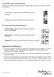
JP1 and JP3 - Power over Serial (pin-9)
Enable or disable power output on pin 9 for the DB9 serial ports S1 to S8 (JP1) and S9
to S16 (JP3).
Disable power output on pin-9 of the DB9 connector
(Default)
Enable power output on pin-9 of the DB connector
JP2 - Power over Serial Voltage Selector
Internal 12V: 12V power is drawn from the PCIe bus
connector (Default)
External 12V: 12V power is drawn from the J3 power
connector
External 5V: 5V power is drawn from the J3 power connector
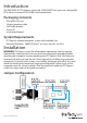
Hardware Installation
1. Turn your computer o and any peripherals connected to the computer (i.e. Printers,
external hard drives, etc.). Unplug the power cable from the rear of the power
supply on the back of the computer.
2. Remove the cover from the computer case. See documentation for your computer
system for details.
3. Locate an open PCI Express slot and remove the metal cover plate on the rear of the
computer case (Refer to documentation for your computer system for details.). Note
that this card will work in PCI Express slots of additional lanes (ie. x4, x8 or x16 slots).