COMMERCIAL GAS WATER HEATER Glass-Lined Tank-Type Water Heater Instruction Manual • INSTALLATION • OPERATION • SERVICE • MAINTENANCE • LIMITED WARRANTY CAUTION TEXT PRINTED OR OUTLINED IN RED CONTAINS INFORMATION RELATIVE TO YOUR SAFETY. PLEASE READ THOROUGHLY BEFORE INSTALLING AND USING THIS APPLIANCE. PLACE THESE INSTRUCTIONS ADJACENT TO HEATER AND NOTIFY OWNER TO KEEP FOR FUTURE REFERENCE. PRINTED IN U.S.A. 0903 PART NO.
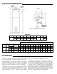
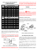
ROUGH-IN-DIMENSIONS DIMENSIONS Model 65 In. mm A 63 1/2 1613 B 61 1550 C 26 660 D 22 559 E 4 106 F 8 203 G 3/4 NPT H 1/2 NPT J 53 3/4 1,365 RECOVERY CAPACITIES RECOVERY CAPACITIES U.S. Gallons/Hrs. and Litres/Hr. at TEMPERATURE RISE INDICATED Model 65 65 Type of Gas Input Approx. Btuh KW Capacity 65,000 65 US Gals. Natural 19.0 246 Litres 55.000 65 US Gals. Propane 16.
TABLE OF CONTENTS Page ROUGH-IN DIMENSIONS ....................................................................... 2 FOREWORD .......................................................................................... 2 GENERAL SAFETY INFORMATION ...................................................... 3 Precautions ....................................................................................... 3 Liquid Petroleum ...............................................................................
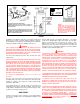
to flow. THERE SHOULD BE NO SMOKING OR OPEN FLAME NEAR THE FAUCET AT THE TIME IT IS OPEN. DO NOT INSTALL THIS WATER HEATER DIRECTLY ON A CARPETED FLOOR. A FIRE HAZARD MAY RESULT. Instead the water heater must be placed on a metal or wood panel extending beyond the full width and depth by at least 3 inches (76 mm) in any direction. If the heater is installed in a carpeted alcove or closet, the entire floor shall be covered by the panel. Also, see the drain requirements.
U.S. REQUIREMENTS KEEP APPLIANCE AREA CLEAR AND FREE OF COMBUSTIBLE MATERIALS, GASOLINE AND OTHER FLAMMABLES, VAPORS AND LIQUIDS. Ratings specified by manufacturers for most appliances apply for elevations up to 2000 feet (610 m). For elevations above 2000 feet (610 m), ratings must be reduced at the rate of 4% for each 1000 feet (305 m) above sea level.
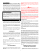
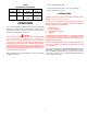
2. Toxic chemicals, such as those used for boiler treatment, shall NEVER be introduced into this system. 3. This unit may NEVER be connected to any existing heating system or component(s) previously used with a non-potable water heating appliance. 4. When the system requires water for space heating at temperatures higher than required for domestic water purposes, a tempering valve must be installed (See Fig. 3).
SINGLE TEMPERATURE VACUUM RELIEF VALVE * INSTALL PER LOCAL CODES CIRCULATING RETURN LINE CONNECTIONS TEMPERED WATER LOOP, IF USED, CONNECT TO POINT "A". STORED TEMPERATURE WATER LOOP, IF USED, CONNECT TO COLD WATER INLET. WARNING TEMPERATURE SETTING SHOULD NOT EXCEED SAFE USE TEMPERATURE AT FIXTURES. SEE TEMPERATURE REGULATION ON PAGE 11. IF HIGHER PREHEAT TEMPERATURES ARE NECESSARY TO OBTAIN ADEQUATE BOOSTER OUTPUT, ADD AN ANTI-SCALD VALVE FOR HOT WATER SUPPLIED TO FIXTURES.
TABLE 1 - GAS SUPPLY LINE SIZES (IN INCHES)* MAXIMUM CAPACITY OF PIPE IN CUBIC FEET PER HOUR LENGTH IN FEET 10 20 30 40 50 60 70 80 90 100 125 150 175 200 LENGTH IN METERS 3 6 9 12 15 18 21 24 27 31 38 46 53 61 1/2" 175 120 97 82 73 66 61 57 53 50 44 40 37 35 1/2" 51 35 28 24 21 19 18 17 16 15 13 12 11 10 3/4" 360 250 200 170 151 138 125 118 110 103 93 84 77 72 NORMAL IRON PIPE SIZES (INCHES) INPUT IN THOUSANDS BTU/HR 1" 1 1/4" 1 1/2" 2" 2 1/2" 3" 680 1400 2100 3960 6300 11000 485 950 1460 2750 4360 770
TABLE 2 MANIFOLD PRESSURE SETTING Model Number 65 Type of Gas Natural 65 Propane Input 65,000 Btu/hr 16.7 KW/hr 55,000 Btu/hr 16Kw Manifold Pressure 4.0 in. W.C. 1.0 Kpa 10.0 in. W.C. 2.49kPa • Entire system filled with water. • Air purged from all lines and no leaks (gas and water). • All gas and water lines open. PRECAUTIONS DO NOT USE THIS APPLIANCE IF ANY PART HAS BEEN UNDER WATER. The heater must be replaced.
FOR YOUR SAFETY READ BEFORE LIGHTING WARNING If you do not follow these instructions exactly, a fire or explosion may result causing property damage, personal injury or loss of life. A. This appliance has a pilot which must be lighted by hand. When lighting the pilot, follow these instructions exactly. B. • If you cannot reach your gas supplier, call the fire department. C. Use only your hand to push in or turn the gas control knob. Never use tools.
TEMPERATURE REGULATION DANGER THIS WATER HEATER IS EQUIPPED WITH AN ADJUSTABLE THERMOSTAT TO CONTROL WATER TEMPERATURE. HOT WATER TEMPERATURES REQUIRED FOR AUTOMATIC DISHWASHER AND LAUNDRY USE CAN CAUSE PAINFUL SCALDING WITH POSSIBLE SERIOUS AND PERMANENT INJURY. THE TEMPERATURE AT WHICH INJURY OCCURS VARIES WITH THE PERSON’S AGE AND THE TIME OF THE EXPOSURE. THE SLOWER RESPONSE TIME OF CHILDREN, AGED OR DISABLED PERSONS INCREASES THE HAZARDS TO THEM.
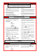
and bathroom exhausts, so they shall operate at maximum speed. Close fireplace dampers. WARNING SOOT BUILD-UP INDICATES A PROBLEM THAT REQUIRES CORRECTION BEFORE FURTHER USE. CONSULT WITH A QUALIFIED SERVICE TECHNICIAN. 4. Follow the lighting instruction. Place the water heater being inspected in operation. Adjust thermostat so appliance shall operate continuously. Should the main burner or burner air openings require cleaning, remove the burner and clean with a soft brush.
diameter core wire is visible as this means that the anode material has been expended in the control of corrosion. Compare the actual input rate to that given on the heater’s rating plate. In the example, the 65 full input rate should be 65,000 Btuh (19.0 KW) for natural gas. NOTE: Anode rod inspection may need to be made more frequently in areas subject to acid rain that obtains their water supply from surface water as the low pH will accelerate anode activity.
4. If the heater was installed when incoming water temperatures were warm, colder incoming temperatures will create the effect of less hot water. quantities of water are drawn, chilling the tank bottom. This too can result in condensation. • 5. The thermostat water temperature adjusting dial may be set too low. 6. If you cannot determine the cause of the problems, contact your dealer. WATER TEMPERATURE IS TOO HOT 1. The thermostat water temperature adjusting dial may be set too high. 2.
NOTES 15