PHOTOVOLTAIK – PHOTOVOLTAICS – PHOTOVOLTAIQUE – FOTOVOLTAICA Installation and operating instructions Solar charge controller Solarix MPPT 010 EN 730.9 7 | 09.10 730.9 7 | 09.
Index 1. About these instructions.........................................................................3 1.1 Applicability.............................................................................................3 1.2 Users........................................................................................................3 1.3. Description of symbols............................................................................3 2. Safety.....................................................
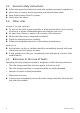
1. About these instructions These operating instructions are part of the product. Read these operating instructions carefully before use, keep them over the entire lifetime of the product, and pass them on to any future owner or user of this product. 1.1 Applicability This manual describes the installation, function, operation and maintenance of the solar charge controller. Further technical information is provided in a separate technical manual. 1.
2.3 General safety instructions Follow the general and national safety and accident prevention regulations. Never alter or remove the factory plates and identification labels. Keep children away from PV systems. Never open the device. 2.4 Other risks Danger of fire and explosion Do not use the solar charge controller in dusty environments, in the vicinity of solvents or where inflammable gases and vapours can occur. No open fires, flames or sparks in the vicinity of the batteries.
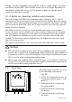
3. Description 3.1 Functions The solar charge controller • monitors the battery voltage, • controls the charging process, • controls the connection/disconnection of loads connected to the load output. This optimises battery use and significantly extends its service life. Solarzellen konv. La A battery charging algorithm protects the battery from harmful states. Activation of the three deep discharge functions (LVW, LVD and LVR) is dependent Uoc upon the battery voltage. Umpp 3.1.
Charge controllers with MPP trackers can be used for a wider range of modules than those without MPPT. With an MPP tracker one is no longer dependent on the module voltage and string size. The module voltage can deviate significantly from the battery voltage. 3.1.4 Notes on choosing suitable solar modules This solar charge controller has a maximum input voltage of 100 V.
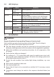
3.3 LED displays LED Info LED Status illuminates green flashes red Red LED flashes quickly battery empty when the battery continues to be discharged the deep-discharge deactivation is triggered flashes deep-discharge deactivation illuminates battery weak Yellow LED Meaning normal operation a fault exists (see "Faults and remedies") flashes switch-on threshold after deep-discharge deactivation has not yet been reached 1. green LED illuminates battery good battery full 2.
4.1. Mounting the solar charge controller 4.1.1 Mounting location requirements • Do not mount the solar charge controller outdoors or in wet rooms. • Do not subject the solar charge controller to direct sunshine or other sources of heat. • Protect the solar charge controller from dirt and moisture. • Mount upright on the wall (concrete) on a non-flammable substrate. • Maintain a minimum clearance of 10 cm below and around the device to ensure unhindered air circulation.
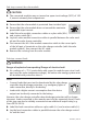
4.2.2 Connection 2 1 3 WARNING Danger of explosion from sparking! Danger of electric shock! At a voltage of > 75 V, particularly with regard to module open circuit voltage (over the entire temperature range), the entire solar energy system must be installed with protection class II. 1st step: connect the battery CAUTION The device will be destroyed if the battery is connected with the wrong polarity. Label the battery connection cables as a plus cable (A+) and a minus cable (A–).
2nd step: connect the solar module CAUTION The connected modules may not exceed an open circuit voltage (VOC) of 100 V, even at extremely low temperatures. Ensure that the solar module is protected from incident light. Ensure that the solar module does not exceed the maximum permissible input current. Label the solar module connection cables as a plus cable (M+) and a minus cable (M–). Lay both solar module connection cables in parallel between the solar module and the solar charge controller.
First connect the L+ load cable to the correct pole of the right pair of terminals on the solar charge controller (with the lamp symbol), then connect the L– cable. Replace the load fuse or switch on the load. 4th step: final work Fasten all cables with strain relief in the direct vicinity of the solar charge controller (clearance of approx. 10 cm). 4.2.
• protection from solar module overcurrent • protection from device overtemperature • protection from overvoltage at the load output • protection from the wrong connection sequence 6. Maintenance The solar charge controller is maintenance-free. All components of the PV system must be checked at least annually, according to the specifications of the respective manufacturers. 12 Ensure adequate ventilation of the cooling element. Check the cable strain relief.
7. Faults and remedies Fault Cause No display • Battery voltage too low • The external fuse in the battery connection cable has blown. • Battery is not connected • Battery is defective Remedy Pre-charge Replace the battery the external fuse 1. Unclamp all connections . Connect a (new) battery with the correct polarity 3.
Load cannot be operated + • Load output is switched off due to too low battery voltage info LED flashes red The load output automatically switched on again as soon as the battery voltage lies within the permissible range Pre-charge + the battery Equip loads directly connected to the battery with deep discharge protection red battery LED flashes Check the battery and replace if necessary Load cannot be • Load output is switched The load output automatioperated off due to excessive battery cal
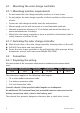
Efficiency example: 100 % 99 % 98 % 97 % 96 % 95 % 94 % 93 % 92 % 91 % 90 % 15 W 730.927 | 09.
8. Technical data MPPT 2010 Characterisation of the operating behaviour System voltage 12 V (24 V) Rated output 250 W (500 W) Max. efficiency > 98 % Own consumption 10 mA DC input side MPP voltage 15 V (30 V) < Umodule << 100 V Open circuit voltage solar module **17 V ... 100 V (34 V ...
NOTE: Technical data that varies from the above is given on a device label. Subject to change without notice. 9. Legal guarantee In accordance with German statutory regulations, there is a 2-year legal guarantee on this product for the customer. The seller will remove all manufacturing and material faults that occur in the product during the legal guarantee period and affect the correct functioning of the product. Natural wear and tear does not constitute a malfunction.
730.927 | 09.
730.927 | 09.
730927