
User manual

10
730.927 | 09.10
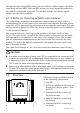
2nd step: connect the solar module
CAUTION
The connected modules may not exceed an open circuit voltage (VOC) of 100
V, even at extremely low temperatures.
Ensure that the solar module is protected from incident light.
Ensure that the solar module does not exceed the maximum
permissible input current.
Label the solar module connection cables as a plus cable (M+)
and a minus cable (M–).
Lay both solar module connection cables in parallel between the solar mod-
ule and the solar charge controller.
First connect the M+ solar module connection cable to the correct pole
of the left pair of terminals on the solar charge controller (with the solar
module symbol), then connect the M– cable.
Remove the covering from the solar module.
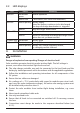
3rd step: connect loads
WARNING
Danger of explosion from sparking! Danger of electric shock!
At a voltage of > 75 V, particularly with regard to module open circuit volt-
age (over the entire temperature range), the entire solar energy system must
be installed with protection class II.
Notes
Connect loads that must not be deactivated by the solar charge
controller deep discharge protection, e.g. emergency lights or
radio connection, directly to the battery.
Loads with a higher current consumption than the device
output can be directly connected to the battery.
However, the solar charge controller deep discharge protection will no longer
intervene. Loads connected in this manner must also be separately fused. Loads
of this type can also be reliably connected via an additional output relay (e.g.
Steca PA EV 200 A).
Label the load connection cables as a plus cable (L+) and a minus cable (L–).
Lay the load connection cables in parallel between the solar charge control-
ler and the load.
•
•