
User manual

8
730.927 | 09.10
4.1. Mounting the solar charge controller
4.1.1 Mounting location requirements
Do not mount the solar charge controller outdoors or in wet rooms.
Do not subject the solar charge controller to direct sunshine or other sources
of heat.
Protect the solar charge controller from dirt and moisture.
Mount upright on the wall (concrete) on a non-flammable substrate.
Maintain a minimum clearance of 10 cm below and around the device to
ensure unhindered air circulation.
Mount the solar charge controller as close as possible to the batteries (with a
safety clearance of at least 30 cm).
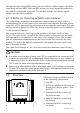
4.1.2 Fastening the solar charge controller
Mark the position of the solar charge controller fastening holes on the wall.
Drill 4 Ø 6 mm holes and insert dowels.
Fasten the solar charge controller to the wall with the cable openings facing
downwards, using 4 oval head screws M4x40 (DIN 7996).
4.2 Connection
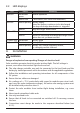
4.2.1 Preparing the wiring
The cross section of the connection cables must be suitable for the currents which
occur.
Modulstrom Batteriestrom Laststrom Querschnitt AWG Isolation
18 A 20 A 10 A 10 mm
2
8 85°C
The table above applies to the following cable lengths:
10 m solar module connection cable
2 m battery connection cable
5 m load connection cable
Consult a dealer if the specified cable lengths are inadequate.
An additional 30 A external fuse (not provided) must be connected to the
battery connection cable, close to the battery pole.
The external fuse prevents dangerous situations due to cable short circuits.
•
•
•
•
•
•
•
•
•