Owner's Manual I_ 5P-fiDS50E WARNING! To Reduce The Risk Of Injury, User 1 FOR SERVICE CALL:Q@@ PAHA SERVIC|Q OOE LLAME: 1818LIm_Li_ EQQt LW_I, Jl,W _ &
Preface This manual will instruct you in the proper operation and service of your diesel generator. Please read this manual prior to using the generatore to ensure safe and proper operation. At all times, follow the instructions to keep the generator in the best working condition and to extend its life. Should you have any comments or problems, please visit your nearest Steele® location or call 1-888-896-6881.
Warning: 1. Preventthe threat of fire o Never add fuel while the engine is running, o Wipe off any spilled fuel with a clean cloth before starting, o Keep all explosive and flammable o Maintain adequate on all sides ventilation of the items safely away from the generator. with at least three feet of clear space generator from buildings and other pieces of equipment. o NEVER operate this unit in a closed room or garage. 2.
o Note: This generator is not waterproof and therefore should not be placed in rain, snow, standing water or any area where there could be water spray. Operating a unit in these environments may cause electrical short circuits that can cause electrical shocks. o This generator should from faulty appliances. also be grounded to prevent electrical shocks To ground this unit, simply connect a length of heavy copper wire between the unit and a ground source.
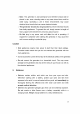
ADANGER CARBON MONOXIDE Using a generator indoors WILL KILL YOU IN MINUTES. Generator exhaust contains high levels of carbon monoxide (CO), a poisonous gas you cannot see or smell• tf you can smell the generator exhaust, you are breathing CO. But even If you cannot smell the exhaust, you could be breathing CO. • NEVER use a generator inside homes, garages, crawtspaces, or other partly enclosed areas. Deadly levels of carbon monoxide can build up in these areas.
1.TechnicalSpecifications andData............................................. 1 2.Configurations 2 3.BeforeStartingYourGenerator ............................................. 4 4.Sta_ingtheGenerator ......................................................... 8 5.OperatingYourGenerator ........................................................ 9 6.YourGenerato_Capacity ......................................................... 10 7.StoppingYourGenerator .....................................................
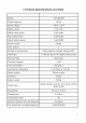
1.Techcial Specifications and Data Model SP-GD650E Rated frequency 60 Hz Rated voltage 240V / 120V Rated current 21A / 42A Rated output power 5,000 watts Max output power 6,500 watts Rated rotation speed 3,600 RPM Phase number Single Pole number 1 Excitation transistorized Panel type Self-excitation constant voltage (AVR) T: General panel TA: Digital control panel Structure type Silent type Fuel tank capacity 4 Gal Fuel consumption 360 g/kw.
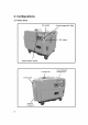
2. Configurations 2.
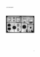
2_2 Control panel 3
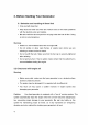
3. Before Starting 3.1 Selection Your Generator and handling of diesel fuel • Only use light diesel fuel • Keep dust and water out of the fuel. Failure to do so will create problems with the injection pump and nozzles. • Do not overfill the tank beyond the red plug inside the fuel oil filter. Doing so can be very dangerous. Warning: • • Refuel in a well-ventilated area with the engine off.
• Oil Selection it is very important that you seiect the prope_ engine oi_ to maintain the life and performance of your generator, engine oil is not replaced if inferior or the wrong weight oil is used, or if your periodically, there is a risk of major damage to your engine due to overheating. Choose the applicable viscosity according to your local temperature.
2, Reattach theairfi_ter cover and tighten the wing nut. Ei_.tmet_t 3.4 Checking the Gene_tor 1. that you turn off the Make sure main switch and any other e{ectrical load before inspecting the generator.
3_5 How to open the cabinet door and remove the protective coven on the gene_tor. t Always open the generator cabinet door and inspect the engine prior to sta_ing the generator. lever To do this, simply turn the counterclockwise and raise the door 2_ Loosen the wing nu_ on the air cleaner and inspect the cieaner. 3.
4. StaGing the Generator Warning: De net plug in any teeis er devils prierte starting yeur g_nerater. 4.1 E_ectric S_rt_ng I Starting ( The preparatiens starting are the same for e_ectric as receiI starting) . O_n the fuel valve ,, Turn the ignition key cleckwise to the "START" pesitien and remove your hand ffem the key as seen as the engine starts, If the engine dees net start in 10 secends just wait 15 secends and re.at Engine starter key 8 the precess.
2. Battery: if the battery has an open ceii design, check the water leve! every month_ If it is _ow, refill using distilled water until the cell is full. If the battery is a sealed unit, check for cracks and Beaks Caution if the distilled water level is too Iow the engine may fail to start because there isn't sufficient surrounding batter.,/ power, if the water ievet is too high, the fluid will corrode parts shortening the _ife of the battery.
the engine will automatically without addressing light illuminates, stop. If you attempt the problem, check the to start the generator the unit will not start. When the "low oil" oil level first to make certain that there is adequate oil in the reservoir. Do not adjust either the engine governor bolt that controls engine speed or the fuel injection performance 5.2 bolt that controls fuel mix. Doing so will affect the overall of your generator.
• When thedualvoltage generator exceeds orisbelow these levels, thenthe circuit breaker should beinthe"OFF" position. Ifnotboth thegenerator andthe devices powered byitcanbedamaged. • Always connect devices tothegenerator withthehighest demand device firstandthenthe lesserdemand devices afterward. If theoperation becomes overloaded, thegenerator engine willlagorstopsuddenly. Ifthis happens, unplug alldevices immediately, turnoffthemainswitch onthe generator andcheck allsystems.
Cauti on • Identify and connect positive-to-positive the battery to the engine, Crossing and the electrical components and negative-to-negative poles from, the wires will destroy both the battery of your generator, • If you attempt to use a larger battery than recommended you will create excessive current that will blow the fuse in the generator, • Do not attempt to operate the generator while it is still connected to the battery, • Do not use a 12V DC and AC current at the same time, Caution
6.3 All electrical have extremely period. appliances, particularly motor driven equipment, highly levels of current draw during their start_up The table below provides a quick reference regarding connecting different types of devices to the generator. WA_AGE EYJ&,MPLE TYPICAL APPLIANCE TYPE STARTING IRATED APPLIANCE RATED _ncandeo scent lamp x1 x1 X2 X_ .5 , Heating In_ndes_nt _amp TV incandescent lamp lOOW 100VA IOOVA (w) (w) 80VA 6OVA (W) (W) appliam ce .
7. Stopping Your Generator Step I: Disconnect aH electrica{ plugs from the generator outiets _fore turning off the generator! Step i1: Turn off the circuit breaker on the generator. Step Ill:: Set the starter lewel in the "run" about three minutes with nothing plugged position, operating the generator in. Note: without this step as the operating temperature for Do Not stop the generator of the engine wih'increase thereby damaging the unit.
8. Periodic Maintenance and Testing Periodic inspections and service are very important for maintaining your generator's engine in proper working order. The fol!owing chart indicates your inspection and _rvice frequency. Please keep this chart handy and refer to it as needed. Warning: • Turn off the engine before performing any servfce.
8.t Replacing the Engine Oil I Operate the engine for two to three minutes without allowing the engine 2 Turn off the engine to get hot. 3. While the engine remove is still swarm_ the oil filter cap and the drain plug located on the bottom of the cylinder block, allowing the old oil to drain, refill with Inse_ the drain plug recommended oil and place the oil fitter cap back on the engine Remember to recycle your oil as it is a major cause of soil poliution_ 8.
I. Turn the fuei vaive to "OFF position. 2. Remove from the smaii screw the fuel valve, removing the fue{ filter from i_s pod. 3. '#'#ash the filter thorougMy with diesei fuel. 4_ Replace the rifler and all pa_s to their origina_ position 8,5 Tightening Tightening the Cylinder Head Bolt the cylinder head requires a special tool Do Not attempt this yourseff! Contact an authorized ser¢_ce _ntre. 8.
8,7 Checking refilling and charging the batte_ Your uses diesei generator battery for starting. Through batte_ may naturaity along with inside. Before starting the batte_ the distilled your check for physical to the batte_ 12V lose some of its charge periodically a use, the water generator_ damage and also the fluid levels, ff is damage, replace it if the fluid levels are Bow,fill each cell with distilIed water as needed.
9. Long-Term Storage If your plan on storing your generator for _riods of time exceeding one month, pRease follow these guidelines: 1, Operate the engine for two to three minutes Do not allow the engine to get hoL 2 Turn offthe engine 3. White the engine is still warm, drain the crankcase oil by opening the oii drain plug. 4. V'vqhenall oii has drained repie_ the plug and refill the oit reservoir with cleanoil, 5.
l O.
APA Part No. Part No.
i 10 13 10 i 1 APA Part No. APG3202-B-01 -TT APG3202-B-02-TT APG3202-B-03-TT APG3202-B-04-TT APG3202-B-05-TT APG3202-B-06-TT APG3202-B-07-TT APG3202-B-08-TT APG3202-B-09-TT APG3202-B-10-TT A PG3202-B- 11-TT A PG3202-B- 12-TT APG3202-B-13-TT 22 Part No.
19 1I 2 APA Part No. IPart No.
Chassis Assembly APA Part No, APG3202-D-01 -TT APG3202-D-02-TT APG3202-D-03-TT APG3202-D-04-TT APG3202-D-05-TT APG3202-D-06-TT APG3202-D-07-TT APG3202-D-08-TT APG3202-D-09-TT APG3202-D-10-TT APG3202- D- 11-TT APG3202-D-12-TT APG3202-D-13-TT APG3202-D-14-TT APG3202-D-15-TT APG3202-D-16-TT APG3202-D-17-TT APG3202-D-18-TT APG3202-D-19-TT APG3202-D-20-TT APG3202-D-21 -TT APG3202-D-22-TT APG3202-D-23-TT APG3202-D-24-TT APG3202-D-25-TT APG3202-D-26-TT APG3202-D-27-TT APG3202-D-28-TT 24 Part No, 951 759-D-01 -
2 2 2 4 2 APA Part No, APG3202-E-01 -TT APG3202-E-02-TT APG3202-E-03-TT APG3202-E-04-TT APG3202-E-05-TT Part No.
APA Part No, APG3202-F-01 -TT APG3202-F-02-TT APG3202-F-03-TT APG3202-F-04-TT APG3202-F-05-TT APG3202-F-06-TT APG3202-F-07-TT APG3202-F-08-TT APG3202-F-09-TT APG3202-F- 10-TT APG3202-F-11 -TT APG3202-F- 12-TT APG3202-F- 13-TT APG3202-F-14-TT APG3202-F- 15-TT APG3202-F- 16-TT APG3202-F-17-TT APG3202-F- 18-TT 26 Part No, 951759-F-01 -TT 951759-F-02-TT 951759-F-03-TT 951759-F-04-TT 951759-F-05-TT 951759-F-06-TT 951759-F-07-TT 951759-F-08-TT 951759-F-09-TT 951759-F-10-TT 951759-F-11 -TT 951759-F-12-TT 951759-
4 APA Part No. APG3202-G-01-TT APG3202-G-02-TT APG3202-G-03-TT APG3202-G-04-TT APG3202-G-05-TT APG3202-G-06-TT APG3202-G-07-TT APG3202-G-08-TT APG3202-G-09-TT Part No.
2 3 4 9 10 ii 15 ]3 i 17 13 22 18 21 19 APA Part No. Part No.
i5 4 3 7 2 / APA Part No, A PG3 202-1-01 -TT A PG3 202-1-02-TT A PG3 202-1-03-TT A PG3 202-1-04-TT A PG3202-1-05-TT A PG3 202-1-06-TT A PG3 202-1-07-'I-IA PG3 202-1-08-TT A PG3 202-1-09-'1-1A PG3 202-1-10-TT A PG3202-1-11 -'I-IA PG3 202-1-12-'I-IA PG3 202-1-13-'1-1A PG3 202-1-14-TT A PG3 202-1-15-3-I- Part No, 951759-1-01-TT 951759-1-02-TT 951759-1-03-TT 951759-1-04-TT 951759- I-05-TT 951759-1-06-TT 95 ! 759-1-07-TT 951759-1-08-TT 951759-1-09-TT 951759-1-10-TT 951759-1-11 -TT 951759-1-12-TT 951759-1-1
14 i2 17 3O APA Part No. Part No.
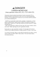
BATTERY INSTALLATION RED BATTERY WIRE _% / THE PRESS PLATE 'k_ OF BATTERY BATTERY ANO l nA 12V BATTERY 7 B_CK BATTERY WIRE _\ BATTERY CATHODE 1. Loosen t:he two bolts on the battery press plate, 2,Take out the battery, 3. Connect the red batte_ wire to the anode, 4. Connect the black batte_ wire to the cathode, 5. Install the battery to the generator according to the drawing.