Model eC3200 TelesCopiC Crane owners’ Manual installation • assembly drawings • parts EC3200 EC 3200 42818 Stellar Industries, Inc. Subject to Change without Notification. © 2012 Stellar Industries, Inc. 190 State Street PO Box 169 Garner, IA 50438 800-321-3741 Fax: 641-923-2811 www.stellarindustries.
EC3200 Manual Revisions Date of Revision Section Revised Description of Revision
Table of Contents Table of Contents Chapter 1 - Specifications . . . . . . . . . . . . . . . . . . . . . . . . . . 1 Capacity Chart - Decal PN 42817 . . . . . . . . . . . . . . . . . . 2 Chapter 2 - Installation . . . . . . . . . . . . . . . . . . . . . . . . . . . . . 3 Installation Overview . . . . . . . . . . . . . . . . . . . . . . . . . . . . . 4 Flatbed Body Reinforcement . . . . . . . . . . . . . . . . . . . . . . 5 EC3200 Mounting Detail . . . . . . . . . . . . . . . . . . . . . . . . . .
ii EC3200 Owner’s Manual This page intentionally left blank.
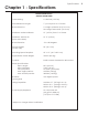
Specifications Chapter 1 - Specifications Model EC3200 Crane SPECIFICATION SHEET Crane Rating: 11,500 ft-lb (1.59 TM) Standard Boom Length: 7’ (2.13 m) from CL of Crane Boom Extension: 1st stage: Hydraulic 48" (121.9 cm) 2nd stage: Manual 48" (121.9 cm) Maximum Horizontal Reach: 15’ (4.57 m) from CL of Crane Maximum Vertical Lift: (from crane base) 16’ 2” (4.93 m) Boom Elevation: -5 to +80 degrees Stowed Height: (crane only) 24” (61.0 cm) Mounting Space Required: 18” x 15” (45.7 x 38.
2 EC3200 Owner’s Manual Capacity Chart - Decal PN 42817 *3200 lbs Reach in Feet/Meters Capacity in Pounds/Kilograms *3025 lbs 1450 kg 16’2” 1372 kg 4.92 M *1550 lbs 15’ 703 KG 3200 lbs 3200 lbs 1450 kg 4.57 M 1090 lbs 1450 kg 495 kg 12’ 2145 lbs 3.66 M 973 kg 3200 lbs 1450 kg 80º 890 lbs 1490 lbs 3200 lbs 404 kg 675 kg 1450 kg 9’ 2.
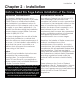
Installation 3 Chapter 2 - Installation Notice: Read this Page Before Installation of the Crane General Installation Installation Notice This chapter is designed to serve as a general guide for the installation of a Stellar EC3200 Crane on a Stellar Service Body. Each installation is considered unique so certain portions of this chapter may or may not apply to your direct application. If a question should arise during the installation process, please contact Stellar Customer Service at (800) 321 3741.
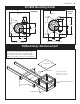
4 EC3200 Owner’s Manual Installation Overview 1. Determine that the mounting location for the EC3200 crane is at least 18” x 15” (45.7 x 38.1 cm). 2. Use the detail on the following page to drill .938” diameter holes into the mounting plate. Run tap on the threads of the base to be sure they are clean. 3. Use a crane or lifting device capable of lifting the weight of the Stellar crane. The Stellar EC3200 weighs approximately 800 lbs (360 kg).
Installation EC3200 Mounting Detail Standard Narrow Base FRONT FRONT 3.00 14.75 10.00 7.38 5.00 7.38 5.00 10.00 14.75 HOLE MOUNTING DETAIL HOLE MOUNTING DETAIL Flatbed Body Reinforcement If it has been determined that the destination body won’t support the crane with a fully rated load, the body must be reinforced. Use 1/4” fillet welds and an ASWS qualified welder to proceed as shown in this drawing: 3/8 PLATE TUBE 4X2X0.38 Note: Tubing must be at least 4” x 2” x 0.
6 EC3200 Owner’s Manual EC3200 Installation Drawing 2 3 NOTICE! Route hoses correctly to ensure they do not become pinched or crushed during installation. Stowed Position ITEM 2 3 PART 18041 51377 D E SC R I P T I O N WASHER 0.88 SAE FLAT YELLOW GR9 CAP SCR 0.88-9X2.00 HHGR9 QTY.
Installation Hydraulic Kit - PN 42799 12 10 11 ROTATION CCW BOOM DOWN ROTATION BOOM UP ROTATION CW MAIN 11 12 10 13 14 11 EXTENSION RETRACT EXTENSION EXTEND EXT 11 EXT OUT EXT IN 04 05 12 12 12 12 12 12 02 06 07 03 MAIN UP ROTATION CCW ROTATION CW MAIN DOWN PN 42799 16 15 14 3861 13 49315 12 C4922 FTG ML FM O'RING 90 DEG SWITCH PRES OVERLD CD-11C-2900R/WD 1 1 FTG ADAPT 4-6 F5OLO-S 8 11 D1291 FTG ADAPT 4-F5OLO-S 4 10 C1111 FTG ADAPT MSTR/FSTR 10-6 F5OG5 2 07
EC3200 Owner’s Manual BA EXT OUT INNER UP ROT CCW BA PRESSURE SWITCH 1 BA P G OW O RO ER O PT1 UN PT D 2 EXT IN INNER DOWN ROT CW Control Kit - PN 42804 BA BA A C A B A B B B A B A 4 9 5 8 B A 6 7 B B A A 3 10 B 12 1 1 12 2 11 2 11 2 B A ER W 10 3 PO A REPLACEMENT CONTROLLER STELLAR P/N 42821 9 4 IT UN R1 7 6 2V GR 4,5,6 Power Unit WINCH DOWN MA CO IN NTA CT B A A B OU ND 87 86 A2B SWITCH WINCH UP WE 8 5 L PO NA SIG 4,5,6 BA 8 7,8 87A 85 30
Installation EC3200 Wiring Diagram (Two Battery) FUSE 250 AMP MASTER SWITCH 250 AMP (STELLAR SUPPLIED) - + (NOT SUPPLIED) TRUCK BATTERY UNDERHOOD CRANE HARNESS CRANE START MOTOR SOLENOID FUSE 250 AMP OPT1 Torque Spec Large Nuts: 35 in-lbs Small Nuts: 15 in-lbs OPT2 (STELLAR SUPPLIED) GROUND GROUND GROUND POST POWER - + AUX BATTERY GROUND LOCATE AUX BATTERY AS CLOSE TO CRANE AS POSSIBLE SWITCH POWER 10 AMP POWER SOURCE FOR RADIO REMOTE CAB OR CRANE COMPARTMENT Recommended Wire Sizes:
10 EC3200 Owner’s Manual EC3200 Wiring Diagram (One Battery) FUSE 250 AMP (STELLAR SUPPLIED) - + TRUCK BATTERY UNDERHOOD CRANE HARNESS CRANE START MOTOR SOLENOID OPT1 Torque Spec Large Nuts: 35 in-lbs Small Nuts: 15 in-lbs OPT2 GROUND GROUND GROUND POST POWER Note: With a single battery configuration, operating the crane when the truck is not running will drain the truck battery.
Installation Valve Bank Drawing ROT CW INNER DOWN EXT IN ROT CCW INNER UP EXT OUT 11
12 EC3200 Owner’s Manual Stability Procedure Definition of Stability for the Stellar Telescopic Crane Products: A truck is stable until the load cannot be lifted off the ground with the winch, without tipping over the truck. Every Stellar crane installed must be tested for stability to determine the actual load capacity of the final truck package. The actual test data must be recorded and supplied with the truck at the time of in-service and should be kept with the truck at all times.
Installation Stability Capacity Chart STABILITY CAPACITY CHART 13
14 EC3200 Owner’s Manual Decal Kit Placement - PN 42816 29 7 14,15 03 EC3200 EC 3200 Indicator Angle 80 70 50 30 20 10 0 01 42818 D1196 60 40 22 25 02 27 9 24 30 26 31 28 PN 42816 *USE THESE DECALS WITH BODY PACKAGE **THESE DECALS NOT INCLUDED WITH THE DECAL KIT **31 18472 DECAL MANUAL OPERATION 1 15 13819 DECAL-ANGLE INDICATOR SS 1 30 42820 DECAL VB CONTROL EC3200 1 14 13820 DECAL ANGLE INDICATOR CS 1 29 35234 DECAL STELLAR MADE IN THE USA 1 *13 C1179 DECAL-E
Assembly Drawings Chapter 3 - Assembly Drawings Base Assembly - PN 42525 4 5 2 3 9 7 10 12 9 11 1 8 6 PN 42525 ITEM 1 2 3 4 5 6 7 8 9 10 11 12 PART 42784 41640 62487 21151 D1307 30750 42 795 D0790 D1345 D1810 C22 5 6 56589 DESCRIPTION BASE EC3200 BEARING SWING DRIVE 170-00058-1 MOTOR 80CC EC3200 YMPH-80-H2(R)-K-S-B GASKET MOTOR 008-10056-1 C AP SCR 0.50-13 X1.25 SH CAP SCR 0.50-13X3.50 HHGR8 STOP SLIDIN G E C3200 WASHE R 0.50 FLAT GR8 FTG CPRSN 0.12NPT/0.25 TUBE TBE AIR SAEJ844 TYPE A .
16 EC3200 Owner’s Manual Base Assembly (Narrow Version) - PN 44613 2 4 11 12 7 10 3 5 8 6 PN 44613 ITEM 1 2 3 4 5 6 7 8 9 10 11 12 PART 44614 41640 62487 21151 D1307 30750 4 2795 D0790 D1345 D1810 C2 25 6 56589 DESCRIPTION QTY. BASE EC3200 NARROW 1 BEARING SWING DRIVE 170-00058-1 1 MOTOR 80CC EC3200 YMPH-80-H2(R)-K-S-B 1 GASKET MOTOR 008-10056-1 1 ref CAP SCR 0.50-13X1.25 SH 2 CAP SCR 0.50-13X3.50 HHGR8 13 STO P SLID ING E C3 200 1 WASHER 0. 50 FLAT GR8 13 FTG CPRSN 0.12NPT/0.
Assembly Drawings Mast Assembly - PN 42787 14 16 5 10 9 22 15 1 * 9 22 10 * 20 9 21 6 4 15 11 7 16 13 12 8 3 3 18 P/N 42798 MUST GO IN THIS MAST MOUNTING HOLE 2 19 NOTE: WINCH CONTROLLER(P/N 42821) SHOWN FOR REFERENCE PN 42787 ITEM 1 2 3 4 5 6 7 8 9 10 11 12 13 14 15 16 18 19 20 21 22 PART 42318 42513 42788 42789 20362 0345 0346 0479 D0917 0478 0340 43579 47411 44475 0343 0420 5870 0492 51896 30659 C6021 DESCRIPTION MAST EC3200 POWER UNIT 12V EC3200 WASHER 0.
18 EC3200 Owner’s Manual Main Boom Assembly - PN 42512 MOUNTING HARDWARE WILL BE PART OF THE WINCH PACKAGE. USE ALL HARDWARE, EXCEPT BOLTS.
Assembly Drawings 19 Extension Boom Assembly - PN 42520 5 6 12 10 11 1 12 11 9 20 18 2 15 22 8 17 7 5 3 3 14 8 15 16 3 16 19 4 21 3 13 PN 42520 I T EM 1 2 3 4 5 6 7 8 9 10 11 12 13 14 15 16 17 18 19 20 21 22 PART 42311 4 2 50 7 D0790 10172 42509 42312 42978PC 4 29 7 7 42317 42524ZP 0423 37824 0507 27710 C6106 0352 35105 D0178 0505 D0561 42505PC 43846 DESCRIPTION EXT BOOM 1ST EC3200 CYLINDER 1.50X48.00 WASHER 0.50 FLAT GR8 CAP SCR 0.50-13X1.00 HHGR8 ZY WEAR PAD 0.38X1.38X1.
20 EC3200 Owner’s Manual Cable & Hook Assembly - PN 42781 8 13 3 4 11 12 11 13 2 5 1 3 1 7 6 10 9 PN 42781 ITEM 1 2 3 4 5 6 7 8 9 10 11 12 13 PART 42523PC 42317 0352 5468 27810 16607PC 47868 42316 9263 C6018 0375 4 2 52 4 Z P 37824 DESCRIPTION PLATE SNATCH BLOCK EC3200 SHEAVE EC3200 5.00 DIA .22R/1.00THK WASHER 0.50 USS FLAT ZINC NUT 0.50-13 HHGR8 NYLOC SPACER 3315 SNATCH BLOCK UHMW SPACER 3315 SNATCH BLOCK CAP SCR 0.50-13X2.75 HHGR8 WIRE ROPE 7/32 7X19 GAC 65FT PIN .38X3.
Assembly Drawings Radio Transmitter Assembly 1 2 7 8 3 5 4 NOTE: 1) P/N'S 25999 & 24958 ARE OPTIONAL COVERS FOR THE SWITCHES AND TRIGGER 6 ITEM 1 2 3 4 5 6 7 8 PART 20088 51830 24385 50932 22600 35441 16975 51831 DESCRIPTION CONTROL HANDLE HOUSING 4 FCTN HET CONTROL HANDLE FACE PLT 5 FCTN GUARD RADIO SWITCH 4 FCTN CONTROL HANDLE GRIP LESS TRIGGER HET H2 SWITCH TOGGLE HET RADIO 63019300 BATTERY TUBE AA HETRONIC RADIO SWITCH E STOP ASM HETRONIC RADIO DECAL CONTROL HANDLE 5 FCTN QTY.
22 EC3200 Owner’s Manual This page intentionally left blank.
Replacement Parts Chapter 4 - Replacement Parts HYDRAULIC COMPONENTS PART# DESCRIPTION 42840 HYDRAULIC SWING MOTOR 21151 GASKET - HYDRAULIC SWING MOTOR 42513 POWER UNIT 12V EC3200 44028 VALVE CARTRIDGE - POWER UNIT 12V #19012-D 44027 VALVE COIL - POWER UNIT 12V #11494-D 44029 MOTOR 12V - POWER UNIT #08111-1 44030 12V SOLENOID (12volt hydraulic system) #17757 44026 HYDRAULIC RESERVOIR - POWER UNIT 12V #14071 44025 FILL CAP - HYDRAULIC RESERVOIR 9803 C-BALANCE VALVE 43892 SEAL KIT - MAIN LIFT CYLINDER 43893
24 EC3200 Owner’s Manual Limited Warranty Statement Stellar Industries, Inc. (Stellar) warrants products designed and manufactured by Stellar to be free from defects in material and workmanship under proper use and maintenance. Products must be installed and operated in accordance with Stellar’s written instructions and capacities.