Operation, Maintenance and Installation Manual Condensate and Boiler Feed Units Sterlco® Steam Control Products A Division of Sterling 2900 S 160th Street New Berlin, WI 53151 Phone: (262) 641-3808 Fax (262) 641-8625 www.steamcontrolproducts.com Part No. 682-89901-00 Revision: S Bulletin No. SCP1-600.
Sterlco® Condensate Pumps Operation and Installation Instructions Operation & Installation Tel (262) 641-3808 • Fax (262) 641-8625 • www.steamcontrolproducts.com • Bulletin: SCP1-600.3 • Effective: July 1, 2008 • Supersedes: August 23, 2005 Selection of Discharge Piping In selecting condensate pumps and making proper piping connections, the friction in the discharge line from the pump to the boiler is very important. The pressure drop due to friction is sometimes much greater than the boiler pressure.
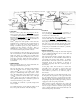
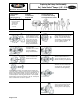
Vent: Pipe Line up to Ceiling then to Floor Drain Float Switch Isolation Valve Isolation Valve Check Valve Vent: Pipe Line up to Ceiling then to Floor Drain Return Cond. Line Strainer Check Valve Isolation Valve Discharge Line to Boiler Isolation Motor & Pump Valve Priming Plug Float Switch Floor Line Cond. By-Pass CleanOut Pipe to Floor Drain Discharge Line to Boiler Return Cond.
Vent: Pipe Line up to Ceiling then to Floor Drain Isolation Valve Return Cond. Line Strainer Motor & Pump Check Valve Isolation Valve Float Switch Floor Line Discharge Line to Boiler Cond. By-Pass Clean Out Pipe to Floor Drain 4100, 4200 and 4300 Series • Electrical Connections Check the motor characteristics (phase, cycles, voltage) to be certain that they are correct for your power supply; otherwise, you may burn out the motor by running it on too high a voltage.
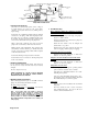
Operation & Installation 1. Motor 2. Water Slinger 3. Motor Bracket Replacing the Rotary Seal Assembly on G Series Sterlco® Pumps: 1/3, 1/2, and 3/4 HP 4. Tube Fitting 5. Motor Screws (4) 6. Pump Screws (4) 7. Rotary Seal Assembly 8. Impeller 9. Impeller Screw REMOVAL OF OLD SEAL ASSEMBLY A) Remove pump housing from motor bracket and impeller assembly by removing pump screws. B) Remove impeller screw and motor screws.
Replacing the Rotary Seal Assembly On J Series Sterlco® Pumps: ½ HP – 3 HP Operation & Installation 1. Motor 2. Water Slinger 3. Bracket 4. Motor Screws (4) 5. Rotary Seal Assembly 6. Impeller 7. Lock Washer 8. Impeller Nut 9. Housing Gasket 10. Pump Screws (8) 11. Vertical Inlet Casting 12.
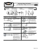
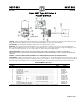
9037-891 9037-891 SERVICE BULLETIN SERVICE BULLETIN Class 9037 Type HG Series A FLOAT SWITCH CAUTION: Switches are shipped with a bracket attached to the mounting plate. This bracket prevents the float and rod from moving in the tank during shipment. When installing the system, this clearly marked shipping bracket must be removed and discarded. APPLICATIONS: For automatically controlling the liquid level in a closed tank by float movement.
9037-891 9037-891 SERVICE BULLETIN SERVICE BULLETIN FLOAT & LINK POSITIONS PRESSURE: In the use of any of these Float Switches, the pressure limit within the closed tank must not exceed 100 lbs. MOTOR PROTECTION: A float switch of this type does not afford motor protection, however it is quite frequently used as a pilot to operate a starter providing these desirable features. The Square D Co. manufactures a complete line of motor protective switches, information on which will be sent upon request.
038-893 9038-893 SERVICE BULLETIN SERVICE BULLETIN Class 9038 Type CG Series A MECHANICAL ALTERNATOR CAUTION: Switches are shipped with a bracket attached to the mounting plate. This bracket prevents the float and rod from moving in the tank during shipment. When installing the system, this clearly marked shipping bracket must be removed and discarded. APPLICATIONS: The Class 9038 Type C Mechanical Alternators serve to open and close an electric circuit by an upward and downward float movement.
9038-893 9038-893 SERVICE BULLETIN SERVICE BULLETIN *WHERE SEPARATE POWER SUPPLIES ARE PROVIDED, THE DISCONNECT MEANS FOR EACH MOTOR MUST BE GROUPED TOGETHER AND PROVIDED WITH SUITABLE WARNINGS IN ACCORDANCE WITH THE NATIONAL ELECTRICAL CODE AND ALL OTHER APPLICABLE CODES AND STANDARDS. CLASS 9038 MECHANICAL ALTERNATOR – WIRING DIAGRAMS* EXPLANATION OF FLOAT TRAVEL AND POSITION NORMAL OPERATION: Switches will cut in and out at the high point and low point of distance A plus B, given in the tables.