SCC 3-Pump 33-Station Controllers Part Number: 882.00252.00 Bulletin Number: CV3-635 Effective: 12/05/05 Write Down Your Serial Numbers Here For Future Reference: _________________________ _________________________ _________________________ _________________________ _________________________ _________________________ We are committed to a continuing program of product improvement. Specifications, appearance, and dimensions described in this manual are subject to change without notice. DCN No.
Please note that our address and phone information has changed. Please reference this page for updated contact information. These manuals are obsolete and are provided only for their technical information, data and capacities. Portions of these manuals detailing procedures or precautions in the operation, inspection, maintenance and repair of the products may be inadequate, inaccurate, and/or incomplete and shouldn’t be relied upon.
Shipping Information Unpacking and Inspection You should inspect your equipment for possible shipping damage. Thoroughly check the equipment for any damage that might have occurred in transit, such as broken or loose wiring and components, loose hardware and mounting screws, etc. In the Event of Shipping Damage According to the contract terms and conditions of the Carrier, the responsibility of the Shipper ends at the time and place of shipment.
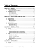
Table of Contents CHAPTER 1: SAFETY ...............................................................VI 1-1 1-2 1-3 How to Use This Manual ............................................................................................ vi Safety Symbols Used in this Manual .................................................................... vi Warnings and Precautions .........................................................................................vii Responsibility ......................................
4-3 4-3 Reviewing Pump Status ......................................................................................30 Logging On and Logging Off ...............................................................................31 Enabling and Disabling Stations and Pumps.......................................................32 Starting and Stopping the System .......................................................................32 Reviewing and Adjusting Basic Station Settings ..............................
Contract Department ...........................................................................................
Chapter 1: Safety 1-1 How to Use This Manual Use this manual as a guide and reference for installing, operating, and maintaining your equipment. The purpose is to assist you in applying efficient, proven techniques that enhance equipment productivity. This manual covers only light corrective maintenance. No other maintenance should be undertaken without first contacting a service engineer. The Functional Description section outlines models covered, standard features, and optional features.
1-2 Warnings and Precautions Our equipment is designed to provide safe and reliable operation when installed and operated within design specifications, following national and local safety codes. This may include, but is not limited to OSHA, NEC, CSA, SPI, and any other local, national and international regulations.
1-3 Responsibility These machines are constructed for maximum operator safety when used under standard operating conditions and when recommended instructions are followed in the maintenance and operation of the machine. All personnel engaged in the use of the machine should become familiar with its operation as described in this manual. Proper operation of the machine promotes safety for the operator and all workers in its vicinity.
Operator Responsibility The operator’s responsibility does not end with efficient production. The operator usually has the most daily contact with the equipment and intimately knows its capabilities and limitations. Plant and personnel safety is sometimes forgotten in the desire to meet incentive rates, or through a casual attitude toward machinery formed over a period of months or years. Your employer probably has established a set of safety rules in your workplace.
Chapter 2: Functional Description 2-1 Models Covered in This Manual This manual provides operation, installation, and maintenance instructions for 3-Pump, 33Station Conveying Controllers. Model numbers are listed on the serial tag. Make sure you know the model and serial number of your equipment before contacting the manufacturer for parts or service.
2-3 Standard Features Mechanical Features Time-fill Capability. The length of time a station’s vacuum valve remains open to allow material to be drawn into its receiver. Volume-fill Capability. The length of time a station’s vacuum valve remains open to allow material to be drawn in. The vacuum valve will close when material covers the station’s volume-fill proximity sensor or this time elapses, whichever comes first. Pump Blowback Filter Cleaning Outputs.
2-5 Safety Devices and Interlocks This section includes information on safety devices and procedures that are inherent to the Controller. This manual is not intended to supersede or alter safety standards established by the user of this equipment. Instead, the material contained in this section is recommended to supplement these procedures in order to provide a safer working environment.
Chapter 3: Installation 3-1 Uncrating 3-Pump, 33-Station Controllers are shipped mounted on a skid, enclosed in a plastic wrapper, and contained in a cardboard box. 1. Pry the crating away from the skid. Note: Remove the nails holding the box to the skid and lift the box off carefully; avoiding staples in the 1’ x 4’ wood supports. Cut the steel banding. 2. Use a pry bar to remove the blocks securing the unit to the skid. 3. Lift unit from sides, inserting forklift under the base.
Connecting the Control Panel to Vacuum Hoppers Note: Wire size depends on control voltage, distance, number of vacuum hoppers, and the number of wires in each raceway. Consult a qualified electrician. 1. On 115 VAC control voltage systems, run a common hot (115 VAC) wire and a common neutral wire from the controller to each vacuum hopper in the system. On 24 VDC control voltage systems, run a common +24 VDC wire and a common 0 (zero) VDC wire from the controller to each vacuum hopper in the system. 2.
3-4 Setup This section provides the procedures for configuring your 3-pump, 33-station controller. Configuration of your controller includes setting the number of stations and pumps, setting variables such as convey time and blow-back interval, and setting up passwords. We recommend that you carry out these procedures in the order given here. Note: Before carrying out these procedures, install all equipment as described in this section and in the Mechanical Components manual.
Figure 3: “System Setup” Screen Before Setup 3. At the “System Setup” screen, (Figure 3), touch Stations Present. A keypad pops up. 4. Enter the total number of stations (1-33) to be controlled by the system. Use (Enter Key) to enter the value. The (Backspace Key) to erase any mistakes. Use keypad disappears, and the new setting appears under Stations Present. 5. Touch Pumps Present. A keypad pops up. 6. Enter the total number of pumps (1-3) to be controlled by the system.
Setting Up Alarm Silences When an alarm occurs, a horn sounds and a strobe light flashes at each installed central alarm. An alarm banner screen appears. An alarm message and Alarm Silence button are on the banner. Touching this button silences the horn and turns off the lights for configurable periods of time and causes the alarm banner to disappear. You can set different lengths of time for keeping the horn silent and keeping the light turned off.
Setting Up Pump Staging To avoid an excessive power demand at your facility when the conveying system starts up, you can stagger the times at which pumps start. Whenever a demand would cause two pumps to start simultaneously, your choice for pump staging sets the delay between the start of one pump and the start of the next. The factory default is a delay of three seconds. You need to change this setting only if this delay is too long or too short for your facility.
Setting Up Stations Before starting the system, you must define several settings for each station, such as which pump conveys material to it. This section first discusses how to use the controller’s menu system to configure stations. The table on pages 42–43 discusses the individual choices. Setting Up a Single Station 1. Go to the “Station Status” screen if needed. To reach this screen from any other screen, touch Menu on the right hand side of the screen, and then touch Stations.
Figure 7: “Station Setup” Screen 4. On the “Station Setup” screen (Figure 7), adjust settings as required. Touching any box that appears in red (for “disabled”) toggles it to green (for “enabled”), and vice versa. Touching any white box gives you a keypad to enter a new value. Touching Reset To Defaults in the lower right of the screen changes all the settings for this station back to their factory defaults. See pp. 41–44 for details on the options and their default settings. 5.
Copying Settings from One Station to Others If other stations at your facility will use the same settings as a station you have already set up, you can copy the settings from this station to the others. To copy settings from one station to others, complete the steps below. • At the “Station Setup” screen (See Figure 7) for the station you want to copy from, touch Copy in the upper right corner. The “Station Copy” screen appears, showing the station number for the station you are copying from.
2. Enter the station number for the lower end of the range you are copying to. Use (Backspace Key) to erase any mistakes. Use (Enter Key) to enter the value. The keypad disappears, and the “Station Copy” screen shows the station number you entered under First Station. 3. On the “Station Copy” screen (Figure 8, touch the gray Last Station button. The keypad pops up. 4. Enter the station number for the upper end of the range you are copying to. Use (Backspace Key) to erase any mistakes.
Setting Up Pumps Before starting the system, you must define several settings for each pump, such as how quickly to shut it down when it is not in use. This section first discusses how to use the controller’s menu system to configure pumps. The table on page 44 discusses the individual choices. Setting Up a Single Pump 1. Go to the “Pump Status“ screen if needed. To reach this screen from any other screen, touch Menu on the right-hand side of the screen, and then touch Pumps.
4. As appropriate, setup the rest of the pumps using either of the following methods: • Copy this pump’s settings to one or more other pumps, as described below • Use the Back or Next buttons to navigate to other pumps. Touch Back to go to the previous “Pump Setup” screen, or touch Next to go to the next “Pump Setup” screen. • Touch Goto and enter a pump number to go to that pump’s setup screen .
4. As appropriate, either continue copying to other pumps, or touch Return to go back to the “Pump Setup” screen. • Copying to a Range of Other Pumps: 1. On the “Pump Copy” screen (Figure 10) touch the gray First Pump button. The keypad pops up. 2. Enter the pump number for the lower end of the range you are copying to. Use (Enter Key) to enter the value. (Backspace Key) to erase any mistakes. Use The keypad disappears, and the “Pump Copy” screen shows the pump number you entered under First Pump. 3.
Operator Password If you define a password for operators, then a password will be required to carry out any function (other than reviewing station and pump status, silencing alarms, reviewing the alarm log, and looking at help screens).
To change the duration of the password, complete the following steps: 1. On the “System Setup” screen (Figure 4), touch the Operator Password Duration button or the Setup Password Duration button, depending on which password duration you want to change. A keypad pops up. 2. Enter the number of minutes (between 1 and 99) that you want to set as the password (Backspace Key) to erase any mistakes. Use (Enter Key) duration. Use to enter the value.
Chapter 4: Operation 4-1 Overview Your 3-pump, 33-station controller electrically controls valves and solenoids to convey material from a central location to individual stations as needed. The controller senses demands for material at the stations and responds to the demands in a timely fashion. This section gives the procedures for using your controller, and it covers tasks that can be carried out with no password or with an operator’s password.
4. When you are finished reviewing the information, touch Return. The “Help Menu” screen opens. 5. Touch Menu to return to the “Menu” screen. The following table explains the status represented by each color at the “Station Status” screen. Color Gray outline Label Offline Blue Yellow Green Light blue Green, blinking Ready Demand Loading Dumping Priority Red, blinking Red outline, blinking Alarm Critical Description Station is not enabled. The controller ignores any demands or alarms.
Reviewing Pump Status The “Pump Status” screen is the counterpart of the “Station Status” screen. To reach the “Pump Status” screen from any other screen, touch Menu on the right-hand side of the screen, and then touch Pumps. The “Pump Status” screen appears. Figure 12: “Pump Status” Screen During Operation The status of each pump is color-coded. You can see an explanation of each status by using the online help. To do so from this screen, complete the following steps: 1. Touch Menu.
Logging On and Logging Off Your controller may be set up to require a password for any operation (other than reviewing station and pump status, silencing alarms, reviewing the alarm log, and looking at help screens). If so, touching a button will open the “Password Entry” keypad screen. Figure 13: “Password Entry” Screen Enter the four-digit password (including any leading zeros). For example, if the password is 1, enter 0001. Each digit appears as an “X” as you touch it.
Enabling and Disabling Stations and Pumps When a station or pump is disabled, the controller makes no attempt to use it and ignores any alarms that occur for it. Disabling a station or pump at the controller’s screen is similar to bypassing a station with its bypass switch. Enabling a station or pump makes it available for use. Note: For a station to be available for the system, it must be enabled at the controller’s screen and its bypass switch must be in the “0” position.
Reviewing and Adjusting Basic Station Settings The 3-pump, 33-station controller has a “Station Operator” screen for each station, as shown below. This screen enables you to review and adjust all basic settings for the station. To reach the “Station Operator” screen, complete the following steps: 1. Go to the “Station Status” screen, if needed. To reach this screen from any other screen, touch Menu, and then touch Stations. 2.
Adjusting Convey Time and Dump Delay Convey time is the length of time the station’s vacuum valve remains open to allow material to be drawn in. (For a volume-fill station, the valve closes when material covers the station’s volume-fill proximity sensor or this time elapses, whichever comes first.) Dump delay is the length of time allowed for material to drain from the station into its receiver. During this time, the controller does not attempt to deliver any more material to the station.
Activating and Stopping Priority Convey for a Station Note: Before activating priority convey, make sure that all other stations using the same pump have adequate material in reserve to continue operation. No material will be conveyed to these stations during priority convey. If you want the controller to fill a specific station with material immediately, you can activate “priority convey” for that station.
4-3 Adjusting Advanced Settings This section describes the procedures carried out during operation that are normally reserved for setup personnel. These procedures require use of the setup password (if your facility has defined one). The procedure for logging on and off with the setup password is the same as for logging on with the operator password; see p. 31 for step-by-step instructions for logging on and off.
Transferring Stations to a Standby Pump If a pump fails, you can transfer all of the controller’s station assignments for that pump to a standby pump. To do this, you must disable (take offline) both the source pump and the standby pump, and the standby pump must have no stations already assigned to it. The transfer operation at the controller’s touch screen merely changes the pump assignment for every station on the failed pump.
9. Enter the number of the standby pump. Use (Backspace Key) to erase any (Enter Key) to enter the value. The number appears under mistakes. Use Standby Pump, and a button labeled Transfer to Standby Pump appears on the screen. Figure 17: Transfer To Standby Pump Button Note: When you enter the second pump number, the controller checks to make sure that both pumps are offline and that the standby pump has no stations assigned to it.
Standby Pump Errors If the error message tells you to disable the source pump and/or the standby pump, touch Return at this screen, then Pumps at the “Pump Setup” screen. Take the pumps offline and then return to the “Transfer to Standby Pump” screen. If the error message tells you that the standby pump has stations assigned, you must either use a different standby pump or you must remove the pump assignment for all stations assigned to the standby pump.
Silencing Alarms Whenever a new alarm occurs, your controller sounds the horn and turns on the strobe light at each central alarm. Touch Alarm Silence on the alarm message banner that appears when a new alarm occurs or press the physical push button included in the central alarm option. The horns and lights at the central alarms turn off. Your controller has separate, configurable settings for how long the horns should remain silent and how long the lights should remain off.
Chapter 5: Maintenance No Periodic maintenance is required on this unit.
Chapter 6: Configurable Settings This section describes the proper setup of the 3 pump, 33-station control system parameters. These parameters are operator changeable; however, these items should require setup only during the initial installation. Only authorized personnel should change them. Many of the variables and setup parameters have been preset at the factory and do not need to be changed.
Name Alarm Options Description Options Default No convey When this option is enabled, the controller issues a “no convey” alarm if it has repeatedly attempted to convey material to the station but the flapper never opened during the dump delay. (The number of attempts is controlled by the next setting.) Usually this option should be enabled. At times, you may wish to disable it during operation as a stopgap measure for dealing with an alarm.
6-2 Options for Pump Setup Several of the items in this screen are not setup options but are instead intended for use during operation. These items (hour meter and transferring stations to a standby pump) are described in Chapter 4, which cover operation procedures. Name Idle Time Options Description Options Default Auto shutdown delay Length of time the pump continues to run unloaded without demand from any station.
Chapter 7: Troubleshooting 7-1 General Troubleshooting Problem The control panel doesn’t light up at all The touch screen display doesn’t come on when the control panel is powered up. A pump package doesn’t run, even though it is on-line and its indicator is lit. A vacuum receiver is being bypassed in the loading cycle. Vacuum hoppers are overfilling. Possible Cause The control panel is not turned on. Solution Turn on the control panel.
7-2 Alarms The format for all station alarms is “Station n [alarm text],” for example, “Station 12 receiver low level.” The format for all pump alarms is “Pump n [alarm text].” Any alarm that does not start with “Station” or “Pump” is a system alarm. The following tables list all alarms alphabetically, together with possible causes. A “critical” alarm is one that causes the affected device to stop. Note: You can also see a list of alarms and their causes in the controller’s online help.
Chapter 8: Appendix 1-1 Warranty The manufacturer warrants all equipment manufactured by it to be free from defects in workmanship and material when used under recommended conditions. The company’s obligation is limited to repair or replace FOB the factory any parts that are returned prepaid within one year of equipment shipment to the original purchaser, and which, in the company’s opinion, are defective. Any replacement part assumes the unused portion of this warranty.
8-3 Drawings and Diagrams Figure 19: 3 pump 33 station Controller with 6" Display 24” 6” 30” * Depth dimension is 12” Also, review electrical drawings supplied in the packet with this manual.
8-4 Spare Parts List AC Voltage Quantity 1 1 1 2 3 4 1 1 Part Number A0563932 A0569862 A0572817 A0569859 A0541611 A0540997 A0540993 A0505812 Description 2.1A Power Supply Input Card Output Card Air Grill with Filter Fuse, MDL – .75 Fuse, MDL – 1 Fuse, MDL – .5 Fuse, MDL – 1.25 DC Voltage Quantity 1 1 1 2 3 4 1 1 8-5 Part Number A0563993 A0551976 A0572817 A0569859 A0540997 A0542204 A0542208 A0544790 Description 10A Power Supply Input Card Output Card Air Grill with Filter Fuse, MDL – 1 Fuse, MDL – 2.
Warranty Returns Prior to the return of any material, authorization must be given by the manufacturer. A RMS number will be assigned for the equipment to be returned. Reason for requesting the return must be given. All returns are to be shipped prepaid. The invoice number and date or purchase order number and date must be supplied. After inspecting the material, a replacement or credit will be given, at the manufacturer’s discretion, if the item is found to be defective in materials or workmanship.
8-8 Technical Assistance (Contact Information) Parts Department Call toll-free 7am–5pm CST [800] 423-3183 or call [630] 595-1060, Fax [630] 475-7005 The ACS Customer Service Group will provide your company with genuine OEM quality parts manufactured to engineering design specifications, which will maximize your equipment’s performance and efficiency. To assist in expediting your phone or fax order, please have the model and serial number of your unit when you contact us.