
Marine Instruments User's Manual


Explanation for Positive field control alternators
Explanation for Negative field control alternators
Let us assume that the system over leaf has a regulator on the positive side of the rotor. then there is one
important fact, and that is because the regulator is between the brush and the positive then the other brush
is connected directly to the negative. also the positive brush has the regulator between it and the 14 v input
supply and can never reach 14 volts due to the 2 volt drop between the input voltage and the field brush
There fore the readings are very obvious, one brush will give between 2-12 volts( depending on the output
voltage of the alternator ). , and the other brush will give 0 volts
Hence in the instructions we come up with this voltage scenario. In this case the field control wire is the
one with 2-12 volts on it
If we want to fit the sterling advanced regulator ( s ) on the drawing, then all we need to do is to introduce
another 14 feed into the field brush. we acheive this by obtaining the voltage via our brown cable ( d+ ) ,
bring it up to the regulator, then through the regulator down the white wire to the field brush, in effect by
pass the standard regulator
This also shows 2 important things
1) if the sterling regulator was to fail open circuit, then the standard regulator simply takes over
2) no matter what you do to the sterling regulator you cannot stop the alternator from working. so if the
alternator is not working it has nothing to do with the Sterling system
Let us assume that the system over leaf has a regulator on the negative side of the rotor. then there is on
important fact, and that is because the regulator is between the brush and the negative, and there is always
at least 1-1.5 volts drop across a regulator, the brush closest to the regulator can never reach 0 volts, it will
always be between 2-about 10 volts. Also the other brush will never be the same voltage as the field brush,
as the voltage must pass through the rotor coil , the end result will be at least another 2 volt drop. The
other brush is connect directly to the output voltage of the alternator.
There fore the readings are very obvious, one brush will give between 2-12 volts, and the other brush will
give about 14 volts ( depending on the output voltage of the alternator.
Hence in the instructions we come up with this voltage scenario
In this case the field wire is the one with 2-12 volts on it
If we want to by pass the standard regulator, all we need to do is put the sterling advanced regulator on the
end of the 2-12 volt wire and give the voltage another path through the sterling regulator to negative, in
this case the standard regulator continues to work and tries to shut down the current, but the sterling
simply offers the current a new route, via our whit wire, up to our regulator then down our black wires to
negative.
This also shows 2 important things
1) if the sterling regulator was to fail open circuit, then the standard regulator simply takes over
2) no matter what you do to the sterling regulator you cannot stop the alternator from working. so if the
alternator is not working it has nothing to do with the sterling system
light
2
4
3
1
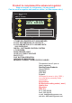
Power Management
with
AMP Hr Counter
Sterling power products
CE
on/off
beep
1
2
3
4
Amp
hr
Amps Volts
13.56 V m CH:1
134 A 345 A/Hr
Key Features:
1 X AMP HR COUNTER UP TO 8000 AMP/HRS
4 X D/C VOLT METER UP TO 199 VOLTS
4 X D/C AMP METER UP TO 199 AMPS WITH
2000 OVERLOAD
DIGITAL , SOFTWARE CONTROL SYSTEM
L.C.D SCREEN
BACK GROUND LIGHT
12 OR 24 V V INPUT VOLTAGE
EASY TO FIT
FLAT BUTTON OPERATION
SURFACE OR RECESS BOX
MEASURE CURRENT IN NEG OR POS CABLES
COMPLETE WITH 1 SHUNT AND FUNCTION LABELS
Product to complement the advanced regulator
This product has a 2 year at
factory warantee
Sterling Power Products
Gregory Mill St
Worcester
WR3 8BA
England
tel 0 1905 26166
fax 0 1905 26155
e mail help@sterling-power.com
web site www.sterling-power.com
We expect to move in July ( 2003 )
to a new factory currently under
construction.
New address
86 Blackpole trading estate ( west )
Hindlip lane
Worcester
WR3 8TJ
Amp hr counter, 4 x volt meters, 4 x amp meters
Can be used in negative and positive cables ( un like anyone else )
Please visit our web page
go to downloads and download the latest
brochure fore other information on battery
chargers, inverters, combined inverters
battery chargers, and much much more
equipment
www.sterling-power.com