
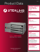
Specification Manual
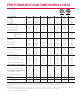


UNIT CAPACITY (MBH) 30 45 60 75 90 105 120
PERFORMANCE DATA†
Input - BTU/Hr 30,000 45,000 60,000 75,000 90,000 105,000 120,000
(kW) (8.8) (13.2) (17.6) (22.0) (26.4) (30.8) (35.2)
Output - BTU/Hr 24,900 37,350 49,800 61,500 73,800 86,100 98,400
(kW) (7.2) (10.9) (14.5) (18.0) (21.6) (25.2) (28.8)
Thermal Efficiency - % 83 83 83 82 82 82 82
Free Air Delivery - CFM 370 550 740 920 1,100 1,300 1,475
(cu. m/s) (.175) (.260) (.349) (.434) (.519) (.614) (.696)
Air Temperature Rise - °F 60 60 60 60 60 60 60
(°C) (15) (15) (15) (15) (15) (15) (15)
Full Load Amps at 120V 3.2 3.2 4.1 4.1 6.4 6.4 6.4
Maximum Circuit Ampacity 3.7 3.7 4.8 4.8 7.5 7.5 7.5
MOTOR DATA: Motor HP 1/20 1/20 1/12 1/12 1/10 1/10 1/10
Motor (kW) (0.04) (0.04) (0.06) (0.06) (0.075) (0.075) (0.075)
Motor Type ODP†† SP SP SP SP SP SP SP
RPM 1650 1650 1050 1050 1050 1050 1050
Motor Amps @ 115V 1.9 1.9 2.6 2.6 4.2 4.2 4.2
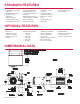
DIMENSIONAL DATA - Inches (mm)
“A” Jacket Height 12-3/8 12-3/8 15-7/8 15-7/8 22-5/8 22-5/8 22-5/8
(314) (314) (403) (403) (574) (574) (574)
“B” Overall Height 13-1/4 13-1/4 16-13/16 16-13/16 23-9/16 23-9/16 23-9/16
(337) (337) (427) (427) (598) (598) (598)
“C” Overall Depth 25-7/8 25-7/8 26-3/16 26-3/16 26-3/8 26-3/8 26-3/8
(632) (632) (665) (665) (670) (670) (670)
“D1” Center Line Height of Flue* 8-1/2 8-1/2 10-3/8 10-3/8 13-5/8 13-5/8 13-5/8
(216) (216) (263) (263) (346) (346) (346)
“D2” Center Line Height of Air Intake 8-1/2 8-1/2 8 8 8-5/8 8-5/8 8-5/8
(216) (216) (203) (203) (219) (219) (219)
“E” Fan Diameter 10 10 14 14 16 16 16
(254) (254) (356) (356) (406) (406) (406)
“F” Discharge Opening Height 10-13/16 10-13/16 14-7/16 14-7/16 21-3/16 21-3/16 21-3/16
(275) (275) (367) (367) (538) (538) (538)
“G” Vent Connection Diameter 4 4 4 4 4 4 4
(102) (102) (102) (102) (102) (102) (102)
“H1” Center Line of Flue Connection From Side
7-1/4 7-1/4 7-1/4 7-1/4 7-3/4 7-3/4 7-1/4
(184) (184) (184) (184) (197) (197) (184)
“H2” Center Line of Air Intake From Side 2-3/4 2-3/4 2-3/4 2-3/4 3-1/2 3-1/2 3-1/2
(70) (70) (70) (70) (89) (89) (89)
VENT SIZE REQUIREMENTS - STANDARD COMBUSTION
Category III Horizontal - Inches (mm) 4 4 4 4 4 4 4
(102) (102) (102) (102) (102) (102) (102)
Category I & III Vertical - Inches (mm) 4 4 4 4 4 4 4
(102) (102) (102) (102) (102) (102) (102)
VENT SIZE REQUIRMENTS - SEPARATED COMBUSTION
Exhaust Diameter - Inches (mm) 4 4 4 4 5 5 5
(102) (102) (102) (102) (127) (127) (127)
Intake Air Diameter - Inches (mm) 4 4 4 4 5 5 5
(102) (102) (102) (102) (127) (127) (127)
Unit Weight - Lbs 60 65 80 85 95 105 110
(kgs) (27) (29) (36) (39) (43) (48) (50)
Shipping Weight - Lbs 70 75 90 95 110 115 120
(kgs) (32) (34) (41) (43) (50) (52) (54)
*For all installations, the flue collar is included with the unit and should be field installed per the instructions included with the unit.
† Ratings shown are for unit installations at elevations between 0 and 2,000 feet (0 to 610m). For unit installations in USA above 2,000 feet (610m), the unit input must be field derated 4% for each
1,000 feet (305m) above sea level; refer to local codes, or in absence of local codes, refer to the latest edition of the National Fuel Gas Code, ANSI Standard Z223.1
(NFPA No. 54).
For installations in Canada, any reference to deration at altitudes in excess of 2,000 feet (610m) are to be ignored. At altitudes of 2,000 feet to 4,500 feet (610 to 1372m), the unit must be field
derated and be so marked in accordance with the ETL certification. See unit installation, operation and maintenance manual for deration information.
†† LEGEND: ODP = OPEN DRIP PROOF SP = SHADED POLE
PERFORMANCE AND DIMENSIONAL DATA