
Product Manual


A/C installation (input to charger)
Wiring, using ring or captive spade connections and a proper crimping tool attach the A/C cables Live ( line ) Neutral and Earth / Ground. Repeat
the procedure for the breaker side of the install, support the cable every 18 inches/ 0.5 metre and protect from sharp edges when passing through
bulkheads and all other openings as per any standards which apply to the installation.
D/C installation (output from charger)
The closer to the batteries you fit the charger the better. Not only
do you save expensive cable you also get better performance from
the charger.
The cable should be properly rated 105 deg C fire resistant. do not
use solid cable or speaker wire
Choosing cable- unlike A/C conductors, D/C are very sensitive to
voltage drop. The longer the cable runs the larger the cable
thickness needs to be, ensure only quality fire retardant cable is
used.
IMPORTANT
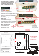
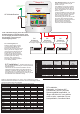
D/C - Fuse selection, as per the
diagram each positive output from the
charger to the battery must be fused.
Choose a fuse that is about 20%
higher amperage rating than the
maximum rating of the charger, and
round it up, remember this fuse is
primarily protecting the cables and not
the product. E.g. a 20 amp charger
would have about a 25 amp fuse, a 60
amp charger about a 75 amp fuse. A
full range of fuses and fuse holders
are available from Sterling.
Ground / bonding / earthing . This is
extremely important and often overlooked
there are, in effect, 3 grounds,
1)the earth wire ( A/C input, the ground ) ,
2) the Chassis / bonding ground ( going to
a vehicle body / boats bonding system,
the bolt on the side of the charger )
3)the D/C negative.
In most installations all these will end up
at the same point, ie the A/C power source
should be connect to the boat/vehicle
chassis ( for safety ).The chassis earth will
also go there, and the D/C neg should
also go there, in effect bonding the total
system together ensuring any fault to the
chassis will blow a fuse. This could vary
for steel/aluminium boats.
Earth /chassis
boats bonding
+
_
12 or 24 v battery bank
+
_
12 or 24 v battery bank
+
_
12 or 24 v battery bank
AC circuit breaker
Any outputs not being used should be linked
across to one that is, this is not a requirement
for these new models but is good practice as it
helps spread loads etc.
D/C fuse
20% larger
amperage than
charger output
D/C fuse
20% larger
amperage than
charger output
D/C fuse
20% larger
amperage than
charger output
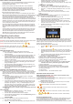
10 amp Length of conductor ( cable ) to and from power source
Distance 3m (10 ft) 5m (15ft) 7m (22ft) 8m (25ft) 9m (30ft)
AWG 14 12 10 10 10
15 amp
Distance 3m (10 ft) 5m (15ft) 7m (22ft) 8m (25ft) 9m (30ft)
AWG 12 10 10 8 8
20 amp
Distance 3m (10 ft) 5m (15ft) 7m (22ft) 8m (25ft) 9m (30ft)
AWG 10 10 8 6 6
30 amp
Distance 3m (10 ft) 5m (15ft) 7m (22ft) 8m (25ft) 9m (30ft)
AWG 10 8 6 6 4
40 amp
Distance 3m (10 ft) 5m (15ft) 7m (22ft) 8m (25ft) 9m (30ft)
AWG 8 6 6 4 4
50 amp
Distance 3m (10 ft) 5m (15ft) 7m (22ft) 8m (25ft) 9m (30ft)
AWG 6 6 6 4 2
60 amp
Distance 3m (10 ft) 5m (15ft) 7m (22ft) 8m (25ft) 9m (30ft)
AWG 6 4 4 2 2
AC BREAKING SIZE
AC input rating
AWG
Cable length
Charger Model
110 Volt
Breaker
220 Volt
Breaker
25ft
(7.6m)
50ft
(15.2m)
100ft
(30.5m)
150ft
(45.6m)
PCU1210 – 2 Output 6 Amp 4 Amp 18 16 14 12
PCU1215 – 3 Outputs 7 Amp 5 Amp 18 16 14 12
PCU1220 – 3 Outputs 8 Amp 6 Amp 18 14 12 10
PCU1230 – 3 Outputs 11 Amp 7 Amp 16 14 10 8
PCU1240 – 3 Outputs 14 Amp 8 Amp
16
12 10 8
PCU1250 – 3 Outputs 16 Amp 10 Amp
14
12 8 8
PCU1260 – 3 Outputs 16 Amp 10 Amp
14
12 8 8
PCU2420 – 3 Output 14 Amp 8 Amp
16
14 10 8
PCU2430 – 3 Outputs 14 Amp 8 Amp
16
14 10 8
There is a 2 year return to factory warranty with all Sterling product
Contact Sterling in Europe or USA. www.sterling-power.com www.sterling-power-usa.com
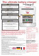
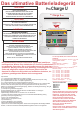
Pro
Charge ULTRA
GLOBAL A/C Input & Active Power Factor Correction
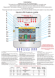
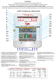
OK
CHARGER MODE
AC Power
Auto Temp Control
Active PFC
Multi Speed Cooling
Volts
Amps
AUTO CONSERVATION MODES
Fault
Absorption
Stand-by
Battery Health Program
Fast Charge
Float
DC Output Service
DC Low Voltage
DC High Voltage Trip
High Charger temp trip
Check Fan
De-sulphation
1 2 3
SETUP
ENTER
CHARGE INFORMATION
Open lead acid
Sealed lead acid
A.G.M
GEL
Calcium / Custom
Lithium (LiFePO4)*
System self test
Battery Type
Charger Output
0% 100%
Progressive DIGITAL software control
RoHS
compliant
High Voltage A/C Low Voltage D/CWARNING
www.sterling-power-usa.com
Preset 1
Preset 2
Sterling Power
www.sterling-power.com
*Lithium must be used in conjunction
with a lithium balancing system.
High current capable of causing sparks burns and
fires, always disconnect the D/C cables from the
batteries before working on the D/C side. Intended
for both COMMERCIAL and DOMESTIC use.
To avoid serious injury or death from electric shock.
Before opening, turn off the main A/C power. Do not
expose to rain nor spray. Replace defective wires/cords
before use. Always read the manual before operating the
charger.
Ground / Chassis
Boat grounding