AV Series AV-25-2 AV-25 Owner’s Manual February 2010 www.stewartaudio.
3. The amplifier should be situated so that its location and position does not interfere with its proper ventilation. For example, the amplifier must not be placed on a rug, bed, sofa or similar surface that impedes airflow across the chassis. Airflow through the ventilation openings should be unobstructed. 4. This amplifier should not be used near water, for example, near a bathtub, in a wet basement, near a swimming pool, etc.
Table of Contents Important Safety Instructions······························································ 2 Table of Contents ················································································ 4 1 Welcome ························································································· 5 1.1 Features ··············································································· 5 1.
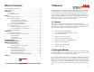
2.2.1 Universal-Mount Installation 2 Setup 2.1 Setup Precautions CAUTION: Before installing your amplifier, make sure that you have read the Important Safety Precautions at the beginning of this manual. The AV 25 also has a universal bracket available which allows the unit to be mounted against a wall or under a table. Two screws are included in the kit which will affix the bracket to the top or the side of the unit. Once this is done, two holes are available for mounting the unit where desired. 2.
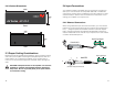
2.2.3 Product Dimensions 2.4 Input Connections 4.35in 11.1cm 1.25in Your AV25-2 amplifier is provided with a 3-pin Phoenix connector for each input. This connector will accept both balanced or unbalanced connections, however some modifications must be made for an unbalanced connection. See the next two sections for instructions on connecting your amplifier to its input source. 3.2cm AV Series AV-25-2 2.4.
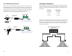
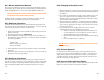
2.4.2 Unbalanced Connections 2.5 Output Connections When using an unbalanced input source and connector, a jumper must be added between the negative (-) terminals and the ground terminals. Once this has been done, the unbalanced source can be connected to the positive (+) and ground terminals. Diagrams have been provided for standard RCA and TS connectors. Please refer to the manual of your input source in case it does not follow the standard pin-out.
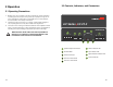
3 Operation 3.2 Controls, Indicators, and Connectors 3.1 Operating Precautions 1. Before use, your amplifier must be configure for proper operation, including input and output wiring hookup. Improper wiring can result in damage to equipment or potentially harm to the operator. Consult section 2 for setup instructions. 2. Tampering with the circuitry, or making unauthorized changes is not only dangerous but may also violate local regulations. 3.
3.2.1 Indicators The AV 25 has 4 rear panel LED indicators. The first is the power indicator which will illuminate when power is supplied to the amplifier. The next 2 LED indicators are the “Clip” indicators, one for each channel. These lights will indicate that the input signal is too “hot” and will sound distorted when amplified. To fix this, the gain should be reduced at the preamp or mixer level.
5 Technical Specifications Maximum Output 30Hz - 20kHz Stereo 25W @ 8Ω per channel 35W @ 4Ω per channel Frequency Response (+0, -3 dB) 30Hz-20kHz Bandwidth +/- 3.0dB 30Hz-30kHz THD+N <0.1% Signal to noise ratio >100dB External Mute 5-12VDC Slew Rate 30V/ms Input Sensitivity 0.5V (-3 dBV) Standard Voltage Gain 28X (26.5dB) Input Impedance (Balance/Unbalanced) 20k Ohms/10k Ohms Sleep, Idle Current Draw, 1/8 Draw 0.005/0.01/0.
6.2.1 Return Authorization Number All returns to the factory for service must be accompanied by a Return Authorization (RA) number. One can be obtained by contacting Stewart Audio at (209) 588-8111 or via e-mail at support@stewartaudio.com. NOTE: Any defective products received without an RA number will be returned to sender at their expense. If Stewart Audio is unable to contact the sender in 14 days, the merchandise will be considered scrap and may be disposed of. 6.2.