
Instruction Manual


- 6 -
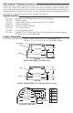
SIDE VIEW
6.2 in.(158mm)
MODELS WITH HORN (STI-1100 Series)
COVER
5.5 in.(140mm)
8.5 in.(216mm)
3.2 in.(81mm)
2 in.(51mm)
ALL MODELS END VIEW
COVER
3.2 in.(81mm)
2 in.(51mm)
5.5 in.(140mm)
5 in.(127mm)
3 in.(76mm)
SPACER
SPACER
SIDE VIEW
7.0 in.(178mm)
MODELS WITHOUT HORN (STI-1200 AND STI-3150 Series)
COVER
6.5 in.(165mm)
8.5 in.(216mm)
3.2 in.(81mm)
2 in.(51mm)
SPACER
3 in.(76mm)
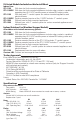
DEPTH CHART FOR STI STOPPER II
4 in.(102mm)
5 in.(127mm)
5.5 in.(140mm)
STI-3100 SPACER
ADDS 2" DEPTH(51mm)
FOR SURFACE MOUNTED
PULL STATIONS
.75 in.(19mm)
1.625 in.(41mm)
2.375 in.(60mm)
2.75 in.(70mm)
3.2 in.(81mm)
5.5 in.(140mm)
HORN HOUSING
3 in.(76mm)
ALL MODELS END VIEW
4 in.(102mm)
5 in.(127mm)
5.5 in.(140mm)
STI-3100 SPACER
ADDS 2" DEPTH(51mm)
5.5 in.(140mm)
E
.75 in.
(19mm)
1.625 in.
(41mm)
2.375 in.
(60mm)
2.75 in.
(70mm)
3.2 in.
(81mm)
A
B
C
D
E
D
C
B
A
PULL DOWN
STI-1280 BACKPLATE
INSERT
(2) PROVIDED
STI-3003 GASKET (1/2 in. CONDUIT)
STI-3004 GASKET (3/4 in. CONDUIT
AND STI-3104 SPACER)
STI-3002 WEATHER GASKET
FOR WEATHER OPTION
(USE TWO WITH SPACER)
STI-3100 CONDUIT SPACER - STANDARD SPACER
INCLUDED WITH SURFACE MOUNT UNITS
STI-3104 CONDUIT SPACER ACCOMMODATES
3/4 in. CONDUIT FOR WEATHER STOPPER
SUB-315 GRILL
SUB-316
LOUVER
*NOTE: STI SUGGESTS USING THE
STI-1280 BACKPLATE FOR WEATHER UNITS
OR WHEN MOUNTED ON AN UNEVEN SURFACE.
WALL
OPTIONAL STI-1103
RELAY BOARD
RED +9, 12, OR 24 VOLTS
BLACK -9, 12, OR 24 VOLTS
GREEN NORMALLY OPEN
BLUE COMMON
WHITE NORMALLY CLOSED
3/32 in. ALLEN WRENCH
(NOT PROVIDED)
SWITCH LOCKING SCREW
5 INCHES OF CABLE IS
PROVIDED FOR SERVICE LOOP.
MAKE SURE THIS LOOP AND
ALL OTHER CABLES DO NOT
INTERFERE WITH STATION
OPERATION.
TO LOCK POWER SWITCH IN
THE "OFF" OR "ON" POSITION
TIGHTEN LOCKING SCREW FULLY
UNTIL SCREW MAKES CONTACT
WITH SWITCH PAD AS SHOWN.
OFF
OPTIONAL RELAY CONTACT SETTINGS
STI MODELS 1100RC, 1130RC, 1150RC AND 1155RC
( NOT USED WITH 9VDC BATTERY JUMPER)
*
*
*
ADDED
SILICONE
EXISTING
PULL STATION
SCREW WITHOUT SPACER
FLUSH MOUNT
WITH OPTIONS
SURFACE MOUNT
WITH OPTIONS
ANCHOR
(4) PROVIDED
EXISTING PULL
STATION
INSERT PLASTIC KNOCK-OUT (2) PROVIDED
INTO SPACER NOTCH IF CONDUIT IS NOT NEEDED
STI-3003 GASKET (USE WITH 1/2 in. CONDUIT)
STI-3004 GASKET (USE WITH 3/4 in. CONDUIT
AND STI-3104 SPACER)
STI-3100 CONDUIT SPACER SHOWN
WITH SUB-316 AND SUB-315
FOR ADDITIONAL VENTILATION
ORDER SUB-316 LOUVER KIT
OR SUB-315 GRILL
SCREW WITH SPACER
BACKPLATE
NOTE: WHEN DRILLING HOLE IN
BACKPLATE NEMA 3R INTEGRITY
IS COMPROMISED
ADHESIVE SIDE
STI-3002 WEATHER GASKETS
INSTALL THICK END OF GASKET
TOWARDS TOP OF ASSEMBLY
STI-1280
BACKPLATE
VIEW OF RELAY CONTACT
15 - 24 VDC
9 - 12 VDC
GROUND
NORMALL OPEN
NORMALLY CLOSED
COMMON
USE ONLY
9 VOLT BATTERY
JUMPER USED ON STANDARD 9
VOLT INTERNALLY
POWERED MODELS
JUMPER INSTALLED ON "RC" MODELS
FOR EXTERNALLY SUPPLIED 12VDC OR
24VDC POWER
NOTE: SMALL CONNECTOR ON JUMPER
FITS INTO PLUG ON RELAY BOARD
THIS JUMPER IS INCLUDED WITH "RC"
MODELS FOR USE WHEN INTERNAL
9VDC BATTERY POWER IS REQUIRED.
(BATTERY NOT INCLUDED)
SMALL CONNECTOR ON JUMPER FITS
INTO PLUG ON RELAY BOARD
USING THIS JUMPER REQUIRES
VOLTAGE SELECTOR SET TO 9V
STI-1103 RELAY
BOARD IS USED ON
"RC" MODELS
VOLTAGE SELECTOR
9V 24V
FACTORY VOLTAGE SETTINGS:
BATTERY POWERED UNITS: 9 VOLT
REMOTE POWER "RC" UNITS: 24 VOLT
USE 24 VOLT SETTING FOR USE WITH
12 VOLT DC INPUT POWER.
VOLUME SELECTOR
LOW
HI
FACTORY VOLUME SETTING: HIGH
USE ONLY
9 VOLT BATTERY
THIS JUMPER IS USED
ON STANDARD 9 VOLT
INTERNALLY POWERED
MODELS
THIS JUMPER IS THE STANDARD
INSTALLED JUMPER ON "RC" MODELS
FOR EXTERNALLY SUPPLIED 12VDC OR
24VDC POWER
NOTE: SMALL CONNECTOR ON JUMPER
FITS INTO PLUG ON RELAY BOARD
THIS JUMPER IS INCLUDED WITH "RC"
MODELS FOR USE WHEN INTERNAL
9VDC BATTERY POWER IS REQUIRED.
(BATTERY NOT INCLUDED)
NOTE: SMALL CONNECTOR ON JUMPER
FITS INTO PLUG ON RELAY BOARD
NOTE: USING THIS JUMPER REQUIRES
VOLTAGE SELECTOR SET TO 9V
STI-1103 RELAY
BOARD IS USED ON
"RC" MODELS
VOLTAGE SELECTOR
9V 24V
VOLTAGE SETTINGS:
STANDARD UNITS: 9 VOLT
"RC" UNITS: 24 VOLT
NOTE: USE 24 VOLT SETTING
FOR USE WITH 12 VOLT DC
INPUT POWER.
VOLUME SELECTOR
LOW
HI
STANDARD VOLUME SETTING: HIGH
FOR RETROFIT APPLICATIONS,
CUT GASKET AT THE BOTTOM TO
INSTALL BEHIND CONDUIT
FOR RETROFIT APPLICATIONS,
CUT GASKET AT THE BOTTOM TO
INSTALL BEHIND CONDUIT
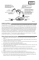
EXPLODED
ELECTRONIC VIEW
Fig. 6
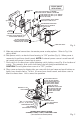
Gasket Installation
Use of gaskets is necessary to ensure a proper seal in weatherproof applications. Weather
Stopper models ship complete with all necessary gaskets and should be used accordingly.
For flush mount weather applications, one STI-3002 must be used between the cover and
wall or backplate (see Fig. 3). In surface mount applications, one STI-3002 must be placed
between the spacer and wall, while another STI-3002 must be placed between the spacer
and cover (see Fig. 4). An STI-3003 or STI-3004 gasket must be used around all entering
conduit. For surface mount applications, it is also recommended that the SUB-315 grill
be installed in the bottom knockout of the conduit spacer. This helps prevent excessive
condensation buildup. STI recommends gasket replacement every five years. (UL requires
listing of pull station to be UL Listed for outdoor installations.)
Battery Replacement Instructions
1. Remove the cover from the frame. It is not necessary to remove the cables from the
frame.
2. Use a 3/32” allen wrench to loosen the button head screw located next to the switch far
enough to slide the switch to the “off” position.
3. Holding the horn housing and cover in one hand, remove the button head screw located
on the top of the cover with the same allen wrench.
4. Set the clear cover aside and remove the horn housing cover.
5. Replace the battery with a 9 Volt battery only. Be careful to keep the wires away from the
slide switch and the micro-switch.
6. Reassemble the unit making sure that the horn housing fits into the tabs on the horn
housing cover; and that this assembly is mounted evenly into the clear cover.
7. Replace the button head screw through the top of the clear cover and into the top of the
horn.
8. Slide the switch to the “on” position. The horn should sound.
9. Push the switch in to silence horn while tightening the “on” position locking screw.
10. Replace the cover onto the frame and test by removing the cover from the frame. The
horn should sound when removed and silence when cover is replaced. If unit does not
operate correctly, contact Safety Technology International, Inc.