
Instructions / Assembly

8 | TEMPRA WWW.STIEBEL-ELTRON-USA.COM
!
NOTICE: THIS UNIT SHOULD NOT BE INSTALLED IN A
LOCATION WHERE IT MAY BE EXPOSED TO FREEZING
TEMPERATURES (LESS THAN 36 °F). IF THE UNIT MAY
BE SUBJECT TO FREEZING TEMPERATURES ALL WATER
MUST BE DRAINED FROM THE UNIT. FAILURE TO COM-
PLY WITH THIS INSTRUCTION VOIDS ALL WARRANTIES.
THE UNIT SHOULD BE LOCATED IN AN AREA WHERE
WATER LEAKAGE FROM THE UNIT OR CONNECTIONS
WILL NOT RESULT IN DAMAGE TO THE AREA ADJACENT
TO THE UNIT. IF SUCH A LOCATION CANNOT BE AVOIDED
IT IT RECOMMENDED THAT A DRAIN PAN BE INSTALLED
UNDER THE UNIT.
1. Install TEMPRA as close as possible to the main hot water draw-
off points.
2. Install TEMPRA in a frost free area. If frost might occur, remove
unit before freezing temperatures set in.
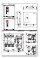
3. Leave a minimum of 5" of clearance on all sides for servicing.
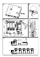
4. Remove the cover screw with a #2 Pozi-drive screwdriver and
open the cover
C
.
5. Mount unit securely to wall by putting at least three screws
through mounting holes
E
1
2
3
4
5
6
7
8
10
11
12
13
14
15
16
17
18
19
20
21
22
23
24
9
-
1
2
3
4
5
6
7
8
10
11
12
13
14
15
16
17
18
19
20
21
22
23
24
9
.
Screws and plastic wall anchors for mounting on masonry or
wood are provided.
5. Water connections
!
NOTICE: EXCESSIVE HEAT FROM SOLDERING ON COPPER
PIPES NEAR THE TEMPRA MAY CAUSE DAMAGE.
THE COLD WATER CONNECTION TO THE UNIT MUST BE
DISCONNECTED PERIODICALLY IN ORDER TO CLEAN THE
FILTER SCREEN. IT IS REQUIRED TO USE WATER CONNEC-
TIONS THAT ARE EASILY DETACHABLE SUCH AS BRAIDED
STEEL FLEX CONNECTORS.
!
NOTICE: HARD WATER OR WATER WITH A HIGH MINERAL
COUNT MAY DAMAGE THE UNIT. DAMAGE TO THE UNIT
CAUSED BY SCALE OR A HIGH MINERAL COUNT IS NOT
COVERED UNDER THE WARRANTY.
1. All plumbing work must comply with national and applicable
state and local plumbing codes.
2. A pressure reducing valve must be installed if the cold water
supply pressure exceeds 150 PSI (10 bar).
3. Make certain that the cold water supply line has been fl ushed
to remove any scale and dirt.
4.
D
Also, the TEMPRA unit has a built in fi lter screen
1
2
3
4
5
6
7
8
10
11
12
13
14
15
16
17
18
19
20
21
22
23
24
9
that
should be cleaned from time to time. Clean screen and put the
screen and the washer
1
2
3
4
5
6
7
8
10
11
12
13
14
15
16
17
18
19
20
21
22
23
24
9
back into their original position.
5. The cold water connection (inlet) is on the right side of the
unit, and the hot water connection (outlet) is on the left side
of the unit.
6.
!
NOTICE: TANKLESS WATER HEATERS SUCH AS THE
TEMPRA ARE NOT REQUIRED TO BE EQUIPPED WITH
A PRESSURE AND TEMPERATURE RELIEF VALVE (P&T).
IF THE LOCAL INSPECTOR WILL NOT PASS THE INSTAL-
LATION WITHOUT A P&T, IT SHOULD BE INSTALLED ON
THE HOT WATER OUTLET SIDE OF THE UNIT.
7. The TEMPRA on the hot side is designed for connection to copper
tubing, PEX tubing or a braided stainless steel hose with a
3/4" NPT female tapered thread.
The plumbing on the cold water inlet side needs to be such that
it can easily be removed to allow access to the inlet fi lter screen.
The easiest way to achieve this is to us a stainless steel
braided hose connector.
If soldering near the unit is necessary, please direct the fl ame
away from the housing of the unit in order to avoid damage.
8. When all plumbing work is completed, check for leaks and take
corrective action before proceeding.
6. Electrical connection
!
WARNING: BEFORE BEGINNING ANY WORK ON THE
ELECTRIC INSTALLATION, BE SURE THAT MAIN BREAK-
ER PANEL SWITCHES ARE "OFF" TO AVOID ANY DANGER
OF ELECTRIC SHOCK. ALL MOUNTING AND PLUMBING
MUST BE COMPLETED BEFORE PROCEEDING WITH ELEC-
TRICAL HOOK-UP. WHERE REQUIRED BY LOCAL, STATE
OR NATIONAL ELECTRICAL CODES THE CIRCUITS SHOULD
BE EQUIPPED WITH A "GROUND FAULT INTERRUPTER".
THE UNIT MUST BE PROPERLY GROUNDED IN ACCOR-
DANCE WITH STATE AND LOCAL CODES, OR IN ABSENCE
OF SUCH CODES, IN ACCORDANCE WITH NATIONAL ELEC-
TRIC CODE OR THE CANADIAN ELECTRIC CODE. FAILURE
TO ELECTRICALLY GROUND THE PRODUCT COULD RESULT
IN SERIOUS PERSONAL INJURY OR DEATH.
1. All electrical work must comply with national and applicable state
and local electrical codes.
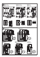
2.
H
The TEMPRA should be connected to properly grounded
dedicated branch circuits of proper voltage rating. Ground must
be brought to the "Ground" at the circuit breaker panel.
TEMPRA 12 B/Plus: These units can be connected to a single cir-
cuit. Use a supply cable protected by a double pole breaker (see
1
2
3
4
5
6
7
8
10
11
12
13
14
15
16
17
18
19
20
21
22
23
24
9
).
The TEMPRAS 15 to 36 must have multiple power sources.
TEMPRA 15, 20 or 24 B/Plus: These units require two independant
circuits. Use two supply cables protected by two separate double
pole breakers (see
1
2
3
4
5
6
7
8
10
11
12
13
14
15
16
17
18
19
20
21
22
23
24
9
).
TEMPRA 29 or 36 B/Plus These units require three independant circuits.
Use three supply cables protected by three separate double pole
breakers (see
1
2
3
4
5
6
7
8
10
11
12
13
14
15
16
17
18
19
20
21
22
23
24
9
).
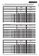
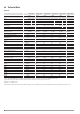
Please refer to the technical data table for the correct wire and circuit
breaker size. In all cases, make sure that the unit is properly grounded.
3. Cut the electrical connection cable to length and strip.
15 (380)
26_02_02_0893
4. The wire must be fed through the knock-outs located between the
hot and cold water connections
A
,
H
1
2
3
4
5
6
7
8
10
11
12
13
14
15
16
17
18
19
20
21
22
23
24
9
. The "live" wires must
be connected to the slots on the terminal block marked L1 and L2.
The ground wire must be connected to slot marked with the ground
symbol (see
I
) .