INSTALLATION GUIDE GUIDE D’INSTALLATION / GUÍA DE INSTALACIÓN Anderson 22 in. Enclosed Ceiling Fan Anderson de 22 po Ventilateur de plafond Ventilador de techo cerrado Anderson de 22 pulg. CF0110 CF0120 CF0130 CF0140 TABLE OF CONTENTS TABLE DES MATIÈRES **************** **************** **************** Important Safety Instructions..................... 2 Instructions importantes concernant la sécurité...................................................
IMPORTANT SAFETY INSTRUCTIONS Do not bend the blade brackets when cleaning the fan. Do not insert foreign objects in between rotating fan blades. WARNING Mount ceiling fan directly to a structural framing member or to a metal outlet box marked “Acceptable for Fan Support of 35 lbs. or less. For outlet box mounting, use mounting screws provided with the outlet box. Read all safety warnings and all instructions.
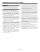
SYMBOLS The following signal words and meanings are intended to explain the levels of risk associated with this product. SYMBOL SIGNAL MEANING DANGER: Indicates a hazardous situation, which, if not avoided, will result in death or serious injury. WARNING: Indicates a hazardous situation, which, if not avoided, could result in death or serious injury. CAUTION: Indicates a hazardous situation, that, if not avoided, may result in minor or moderate injury.
PACKAGE CONTENTS WARNING: WARNING: Items in this section are not assembled to the product by the manufacturer and require installation. Use of a product that may have been improperly assembled could result in serious personal injury. If any parts are damaged or missing, do not operate this product until the parts are replaced. Use of this product with damaged or missing parts could result in serious personal injury.
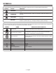
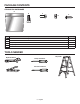
PACKAGE CONTENTS CEILING FAN HARDWARE A B Part C D Description of Enclosed Installation Hardware E Quantity A Canada installation hardware bag 1 B Wire nuts 6 C Phillips cap screws 4 D Phillips cap screw covers 4 E Remote control wall mount screws 2 TOOLS NEEDED Adjustable wrench Step ladder Phillips screwdriver Flat head screwdriver 10 12 14 STRIP LOOP 22 20 18 16 WIREGAGE PLERS Wire cutters/Strippers 5 - English
PRODUCT SPECIFICATIONS Speeds.............................................Hi - 1,400 r/min. (RPM) Med - 940 r/min. (RPM) Low - 500 r/min. (RPM) Airflow (cubic feet per minute)......................Hi - 1,437 CFM Med - 830 CFM Low - 445 CFM Input.......................120 V, AC only, 60 Hz, 0.61 Amps Max. Net Weight.................................................... approx. 24 lbs. Ceiling Clearance Distance.......................................10.4 in. Ceiling Mount Options.............................
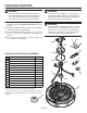
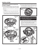
INSTALLATION INSTALLING THE CEILING FAN MOUNTING BRACKET ASSEMBLY The mounting bracket assembly, canopy, and the canopy screw cover ring are assembled together for shipping purposes. If you haven’t already done so, separate these pieces now. • Twist the canopy screw cover ring counterclockwise to release. Remove any existing ceiling fan or light where you intend to install this ceiling fan. Verify the existing outlet box is marked acceptable for fan support up to 35 lbs.
INSTALLATION PREPARING YOUR CEILING FAN FOR MOUNTING Loosen the screw securing the pivot ball to the downrod. Slide the pivot ball down and off the downrod and set aside. Remove the screw and star washer securing the ground wire terminal to the downrod. Remove the wire and set aside.
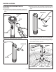
INSTALLATION Thread the downrod into the motor housing until it bottoms out, then back it out until the hole in the downrod aligns with the hole in the motor housing. Be careful not to twist the electrical wiring when tightening. Carefully feed the fan’s electrical wiring through the motor housing cap, then install the cap as shown. MOTOR HOUSING CAP MOTOR HOUSING HOLE Carefully feed the fan’s electrical wiring through the center arm support, then install the support with the cupped side facing up.
INSTALLATION This step is needed only if you are installing your ceiling fan using an extended-length downrod (not provided) and have installed the center arm support from the previous step. If you are using the downrod provided in this package, or if you are using an extended-length downrod but chose not to install the center arm support, skip this step and proceed directly to installing the canopy screw cover ring and canopy.
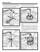
INSTALLATION Carefully feed the fan’s electrical wiring through the pivot ball, then reinstall the pivot ball on the downrod with the flat side facing the ceiling. Reinstall the retainer pin in the downrod. DOWNROD DOWNROD PIVOT BALL FLAT SIDE UP RETAINER PIN For Canada installations, refer to the Canada Installation Addendum and install the support cable on the retainer pin now. Lift the pivot ball back to the top of the downrod until the retainer pin is captured. Tighten the screw to secure.
INSTALLATION Verify the DIP switches on the receiver and the remote control are both in the same configuration. HANGING THE CEILING FAN NOTE: The switches can be adjusted as needed to avoid possible interference with other remote units in your home, but always make sure that the same configuration is set on both the remote and the receiver. WARNING: Once you begin the process of hanging the ceiling fan, do not leave the fan unattended until the installation process is complete.
INSTALLATION MAKING THE ELECTRICAL CONNECTIONS WARNING: Verify the power has been disconnected to both the room and the wall switch before making the electrical connections. Failure to do so could cause fire, electric shock, serious personal injury, or death. MOUNTING BRACKET BLACK GROUND CONDUCTOR WHITE NOTICE: When shipped, the electrical wires from the ceiling fan offer enough length to accommodate extendedlength downrods up to 48 in. (not included).
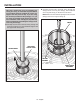
INSTALLATION Place the receiver into the top of the mounting bracket with the flat side facing the ceiling. Tuck the receiver antenna and all wiring up into the mounting bracket, making sure the wires don’t become pinched. Lift the screw cover ring up over the screws and twist counterclockwise to secure in place. SCREWS SLIDES IN FROM THIS DIRECTION ANTENNA MOUNTING BRACKET 4 RECEIVER TOP SCREW COVER RING Slide the canopy up into place and rotate clockwise to lock to mounting bracket assembly.
INSTALLATION Finish the assembly by screwing the finial screw on each arm into the threaded holes in the top lens cover. NOTICE: The decorative arms in the next two steps are not required for fan operation. You may skip these two steps if you do not wish to install the decorative arms. DECORATIVE ARM Install the decorative arms using a Phillips head screwdriver. Attach one side of each arm to the center arm support using the Phillips cap screws and screw covers as shown.
OPERATION USING THE REMOTE CONTROL To mount the remote control holder: NOTE: If you have not already done so, restore power to the room and wall switch, then make sure the wall switch controlling the fan is turned on. The remote control will have no effect on the fan if the switch is turned off. Remove the screw cover from the remote control holder. Install the two AAA batteries provided into the remote control.
OPERATION SETTING THE AIRFLOW DIRECTION Choosing the correct airflow direction of the ceiling fan will enhance the fan’s performance and make its use more enjoyable. To change the direction of airflow, use the direction switch on top of the ceiling fan’s housing. In cooler weather, choose the UP position to provide an upward direction of air travel. This will help circulate warm air off the ceiling and back down into the room.
MAINTENANCE GENERAL CARE AND CLEANING RECESSED AREA ON MOTOR SHAFT Due to the natural movement of a ceiling fan, connections can become loose over time. Check all the ceiling fan’s connections (not including the electrical connections) at least twice a year. The fan has permanently lubricated sealed bearings, therefore no further lubrication is required. Clean your fan periodically to help maintain its new appearance over time.
TROUBLESHOOTING WARNING: Turn off power to room and wall switch by removing fuses or turning off circuit breakers as needed before attempting any repairs to the ceiling fan or the electrical connections. Failure to do so can cause serious personal injury. PROBLEM Fan will not start. POSSIBLE CAUSE Wall switch is turned off. Turn wall switch on. Circuit breaker is tripped or fuse is blown. Reset circuit breaker or replace fuse. Ceiling fan wiring is incorrect.
WARRANTY Limited Lifetime Warranty WHAT THIS WARRANTY COVERS: For the original purchaser only, your Stile™ ceiling fan motor is warranted to be free of material and workmanship defects for the lifetime of the fan motor. All other ceiling fan parts are warranted to be free of material and workmanship defects for a period of one year. HOW TO GET SERVICE: To obtain replacement parts or servicing under warranty, please contact a service representative at One World Technologies, Inc.
NOTES / NOTAS 21
INSTRUCTIONS IMPORTANTES CONCERNANT LA SÉCURITÉ Si cet appareil doit être installé au-dessus d’une baignoire ou d’une douche, il doit convenir à cette utilisation et être relié à un disjoncteur de fuite à la terre (il faut absolument utiliser) – circuit de dérivation protégé. AVERTISSEMENT Lire toutes les mises en garde et directives aux présentes. Tout manquement aux mises en garde et aux directives aux présentes peut résulter en un choc électrique, un incendie et (ou) des blessures graves.
SYMBOLES Les termes de mise en garde suivants et leur signification ont pour but d’expliquer le degré de risques associé à l’utilisation de ce produit. SYMBOLE SIGNAL SIGNIFICATION DANGER : Indique une situation dangereuse qui, si elle n’est pas évitée, aura pour conséquences des blessures graves ou mortelles. AVERTISSEMENT : Indique une situation dangereuse qui, si elle n’est pas évitée, pourrait entraîner des blessures graves ou mortelles.
CONTENU DE L’EMBALLAGE AVERTISSEMENT : AVERTISSEMENT : Les articles dans cette section ne sont pas assemblés au produit par le fabricant et nécessitent d’être installés. Le fait d’utiliser un produit qui a été assemblé de façon inadéquate peut entraîner des blessures. Ne pas essayer de modifier cet outil ou de créer des pièces ou accessoires non recommandés.
CONTENU DE L’EMBALLAGE PIÈCES DE FIXATION DU VENTILATEUR DE PLAFOND A B Num.
FICHE TECHNIQUE Vitesses ................... Élevée – 1 400 révolutions/min (r/min) Moyenne – 940 révolutions/min (r/min) Faible – 500 révolutions/min (r/min) Débit d’air ........................................Élevée – 1 437 pi³/min (pieds cubes à la minute) Moyenne – 830 pi³/min Faible – 445 pi³/min Entrée................. 120 V c.a. seulement, 60 Hz, 0,61 A max. Poids net..........................................................environ 24 lb Dégagement avec le plafond...................................
INSTALLATION INSTALLATION DE L’ENSEMBLE SUPPORT DE MONTAGE DU VENTILATEUR L’ensemble support de montage, la monture et la bague cache-vis de la monture sont assemblés aux fins d’expédition. Si vous ne l’avez pas déjà fait, séparer ces morceaux dès maintenant. • Tourner la bague cache-vis de la monture dans le sens contraire des aiguilles d’une montre pour la dégager. • Desserrer les deux vis situées dans les fentes de la monture.
INSTALLATION PRÉPARATION DU VENTILATEUR DE PLAFOND POUR LE MONTAGE Desserrer la vis retenant la bille d’articulation à la tige. Faire glisser la bille d’articulation vers le bas pour l’enlever de la tige et la mettre de côté. Retirer la vis et la rondelle étoilée qui servent à fixer la borne du fil de mise à la terre à la tige. Retirer le fil et le mettre de côté.
INSTALLATION Visser la tige dans le boîtier du moteur jusqu’à ce qu’elle atteigne le fond, puis la faire ressortir jusqu’à ce que l’orifice sur la tige soit aligné avec l’orifice dans le boîtier du moteur. Veiller à ne pas tordre le câblage électrique au moment de serrer. Insérer soigneusement le câblage électrique du ventilateur dans le capuchon du boîtier du moteur, puis installer le capuchon, comme l’illustre la figure.
INSTALLATION Cette étape est nécessaire uniquement si vous installez votre ventilateur de plafond en utilisant une tige-rallonge (non fournie) et que vous avez installé le support du bras central de l’étape précédente. Si vous utilises la tige fournie dans cet emballage ou si vous utilisez tige-rallonge, mais choisissez de ne pas installer le support du bras central, vous pouvez sauter cette étape et passer directement à l’installation de la bague cache-vis de la monture et de la monture.
INSTALLATION Insérer soigneusement le câblage électrique du ventilateur dans la bille d’articulation, puis réinstaller la bille d’articulation sur la tige, côté plat vers le plafond. Réinstaller la goupille de retenue dans la tige. TIGE TIGE BILLE D’ARTICULATION, CÔTÉ PLAT VERS LE HAUT GOUPILLE DE RETENUE Pour les installations au Canada, consulter l’addenda Installation au Canada et installer le câble de soutien sur la goupille de retenue dès maintenant.
INSTALLATION S’assurer que les commutateurs DIP du récepteur et de la télécommande sont configurés de la même manière. SUSPENSION DU VENTILATEUR DE PLAFOND AVERTISSEMENT : Une fois que vous commencez à suspendre le ventilateur de plafond, ne le laissez pas sans surveillance jusqu’à ce que le processus d’installation soit terminé. La chute d’un ventilateur pourrait causer des blessures graves ou la mort.
INSTALLATION CONNEXIONS ÉLECTRIQUES AVERTISSEMENT : S’assurer que le courant a été coupé de la pièce et de l’interrupteur mural avant de procéder aux connexions électriques. Tout manquement à cette directive pourrait causer un incendie, des chocs électriques, des blessures graves ou la mort.
INSTALLATION Placer le récepteur dans le haut du support de montage, côté plat vers le plafond. Replier l’antenne du récepteur et tout le câblage dans le support de montage en vous assurant de ne pas coincer les fils. GLISSE À PARTIR DE CETTE DIRECTION Remonter la bague cache-vis sur les vis et tourner dans le sens contraire des aiguilles d’une montre pour fixer en place.
INSTALLATION AVIS : Les bras décoratifs dont il est question dans les deux prochaines étapes ne sont pas nécessaires au fonctionnement du ventilateur. Vous pouvez sauter ces deux étapes si vous ne désirez pas installer les bras décoratifs. Installer les bras décoratifs en utilisant d’un tournevis a tête cruciforme. Fixer un côté de chaque bras au support du bras central en utilisant les vis à creux Phillips et les capuchons comme l’illustre la figure.
UTILISATION UTILISATION DE LA TÉLÉCOMMANDE Installation du support de télécommande : NOTE : Si vous ne l’avez pas déjà fait, rétablir le courant dans la pièce et l’interrupteur mural, puis s’assurer que l’interrupteur mural qui contrôle le ventilateur est sous tension. La télécommande n’aura aucune incidence sur le ventilateur si l’interrupteur est hors tension. Enlever le cache-vis du support de télécommande.
UTILISATION DÉTERMINER LA DIRECTION DU DÉBIT D’AIR Le choix de la bonne direction du débit d’air du ventilateur de plafond améliore le rendement du ventilateur et rend son utilisation plus agréable. Pour changer la direction du débit d’air, utiliser l’interrupteur d’orientation situé sur le dessus du boîtier du ventilateur de plafond. Par temps frais, choisissez la position UP (relevée) pour fournir un débit d’air vers le haut.
ENTRETIEN ENTRETIEN ET NETTOYAGE GÉNÉRAL OUVERTURE DE L’ARBRE DES PALES En raison du mouvement naturel d’un ventilateur de plafond, les connexions peuvent devenir lâches au fil du temps. Vérifier toutes les connexions du ventilateur de plafond (à l’exception des connexions électriques) au moins deux fois par année. Le ventilateur est doté de roulements à billes lubrifiés scellés, par conséquent aucune lubrification n’est requise.
DÉPANNAGE AVERTISSEMENT : Couper l’alimentation de la pièce et de l’interrupteur mural en enlevant les fusibles ou en mettant les disjoncteurs hors tension au besoin avant de commencer à réparer le ventilateur de plafond ou les connexions électriques. Tout manquement à cette directive peut causer des blessures graves. PROBLÈME Le ventilateur ne démarre pas. CAUSES POSSIBLES L’interrupteur mural est hors tension. Mettre l’interrupteur mural sous tension. Le disjoncteur a sauté ou le fusible est brûlé.
GARANTIE Garantie limitée à vie ÉLÉMENTS COUVERTS PAR LA PRÉSENTE GARANTIE : Pour l’acheteur d’origine seulement, le moteur de votre ventilateur de plafond StileMC est garanti exempt de défauts de matériaux et de fabrication pendant toute sa durée utile. Toutes les autres pièces du ventilateur de plafond sont garanties exemptes de défauts de matériaux et de fabrication défauts pendant une période de un an.
INSTRUCCIONES DE SEGURIDAD IMPORTANTES No doble los soportes de las hojas cuando limpie el ventilador. No inserte objetos ajenos entre las hojas del ventilador mientras rotan. ADVERTENCIA Lea todas las advertencias de seguridad y todas las instrucciones. No seguir las advertencias e instrucciones podría resultar en electrocución, incendio y/o lesiones graves. LEA Y GUARDE ESTAS INSTRUCCIONES Utilice esta unidad sólo en la forma prevista por el fabricante. Si tiene preguntas, contacte al fabricante.
SÍMBOLOS Las siguientes palabras de señalización y sus significados tienen el objeto de explicar los niveles de riesgo relacionados con este producto. SÍMBOLO SEÑAL SIGNIFICADO PELIGRO: Indica una situación peligrosa, la cual, si no se evita, causará la muerte o lesiones serias. ADVERTENCIA: Indica una situación peligrosa, la cual, si no se evita, podría causar la muerte o lesiones serias. PRECAUCIÓN: Indica una situación peligrosa, la cual, si no se evita, podría causar lesiones menores o leves.
CONTENIDO DEL PAQUETE ADVERTENCIA: ADVERTENCIA: El fabricante no ensambla en el producto los artículos de esta sección, por lo que es necesario instalarlos. El uso de un producto que pueda haber sido armado de manera incorrecta podría provocar lesiones personales graves. No intente modificar este producto ni crear aditamentos o accesorios que no estén recomendados para usar con este producto.
CONTENIDO DEL PAQUETE ACCESORIOS DEL VENTILADOR DE TECHO A B Núm.
ESPECIFICACIONES DEL PRODUCTO Velocidades...................................Alta - 1 400 r/min. (RPM) Media - 940 r/min. (RPM) Baja - 500 r/min. (RPM) Flujo de aire.......................... Alta - 1 437 Pies cúbicos/min. Media - 830 Pies cúbicos/min. Baja - 445 Pies cúbicos/min. Entrada.................. 120 V, solo CA, 60 Hz, 0,61 Amps Máx. Peso neto.............................................aprox. 10 kg (24 lbs) Distancia de separación del techo....... 264 mm (10,4 pulg.
INSTALACIÓN INSTALACIÓN DEL ENSAMBLE DEL SOPORTE DE MONTAJE DEL VENTILADOR DE TECHO El ensamble del soporte de montaje, la cubierta y el aro decorativo atornillado en la cubierta se ensamblan juntos por motivos de envío. Si aún no lo hace, separe estas piezas ahora. Retire los ventiladores de techo o luces existentes cuando intente instalar este ventilador de techo.
INSTALACIÓN PREPARACIÓN DEL VENTILADOR DE TECHO PARA EL MONTAJE Suelte los tornillos que fijan el pivote de rótula a la varilla. Deslice el pivote de rótula hacia abajo, sáquelo de la varilla y déjelo a un lado. Quite el tornillo y la arandela de estrella que fija el terminal del cable a tierra a la varilla. Quite el cable y déjelo a un lado. ARANDELA DENTADA PIVOTE DE RÓTULA TORNILLO TORNILLO TERMINAL DE CABLE A TIERRA VARILLA VARILLA Quite el pasador de retención de la varilla.
INSTALACIÓN Enrosque la varilla en el motor de la caja hasta el tope y retroceda hasta que el orificio de la varilla se alinee con el orificio de la caja del motor. Tenga cuidado de no torcer el cableado eléctrico al apretar. Introduzca con cuidado el cableado eléctrico del ventilador por la tapa de la caja del motor e instale la tapa como se muestra.
INSTALACIÓN Este paso es necesario solo si instalará su ventilador de techo utilizando una varilla de extensión (no incluida) y ha instalado el soporte del brazo central del paso anterior. Si usa la varilla proporcionada en este paquete o si usa una varilla de extensión, pero decide no instalar el soporte de brazo central, Sáltese este paso y siga directamente a la instalación del aro decorativo atornillado en la cubierta y la cubierta.
INSTALACIÓN Con cuidado, introduzca el cableado eléctrico del ventilador por el pivote de rótula, luego vuelva a instalar el pivote de rótula en la varilla con el lado plano mirando hacia el techo. VARILLA Vuelva a instalar el pasador de retención en la varilla.
INSTALACIÓN COMO COLGAR EL VENTILADOR DE TECHO ADVERTENCIA: Una vez que comience el proceso de colgar el ventilador de techo, no descuide el ventilador hasta que finalice el proceso de instalación. La caída del ventilador podría causar lesiones personales graves o la muerte. Verifique que los interruptores DIP del receptor y el control remoto tenga la misma configuración.
INSTALACIÓN CÓMO REALIZAR LAS CONEXIONES ELÉCTRICAS ADVERTENCIA: Verifique que se haya desconectado la energía eléctrica en la habitación y el interruptor de la pared antes de realizar las conexiones eléctricas. No hacer esto podría causar un incendio, choque eléctrico, lesiones personales graves o la muerte. SOPORTE DE MONTAJE NEGRO CONDUCTOR DE TIERRA BLANCO AVISO: Conecte el ventilador del techo receptor: Conecte el cable negro del ventilador de techo al cable negro del receptor marcado TO MOTOR L.
INSTALACIÓN Ubique el receptor en la parte superior del soporte de montaje con helado plano mirando hacia el techo. Coloque la antena y todo el cableado en el soporte de montaje, asegurándose de no aplastar los cables. Levante el aro decorativo atornillado sobre los tornillos y gire el sentido antihorario para fijarlo su lugar.
INSTALACIÓN Termine el ensamble atornillando el último tornillo en cada brazo en los orificios roscados de la cobertura superior. AVISO: Los brazos decorativos de los siguientes dos pasos no son necesarios para el funcionamiento del ventilador. Se puede saltar estos dos pasos y no desea instalar los brazos decorativos. Instale los brazos decorativos utilizando un destornillador de cabeza Phillips.
FUNCIONAMIENTO USO DEL CONTROL REMOTO Para montar el soporte de control remoto: NOTA: Si aún no lo hace, restaure la energía de la habitación y el interruptor de pared, y asegúrese de que el interruptor que controla el ventilador esté encendido. El control remoto no tendrá efecto en el ventilador si el interruptor está apagado. Quite el tornillo de cierre del soporte del control remoto. Instale las dos pilas AAA suministradas en el control remoto.
FUNCIONAMIENTO AJUSTE DE LA DIRECCIÓN DEL FLUJO DE AIRE Seleccionar la dirección del flujo de aire correcta del ventilador de techo mejorará el rendimiento del ventilador y hará que su uso sea más agradable. Para cambiar la dirección del flujo de aire, use interruptor de dirección en la parte superior de la cubierta del ventilador. En climas más fríos, seleccione la posición UP para obtener una dirección de flujo de aire hacia arriba.
MANTENIMIENTO CUIDADO Y LIMPIEZA GENERAL ÁREA EMPOTRADA DEL EJE DE LA HOJA Debido el movimiento natural de un ventilador de techo, las conexiones se pueden soltar con el tiempo. Revise todas las conexiones del ventilador de techo (sin incluir las conexiones eléctricas) al menos dos veces al año. El ventilador tiene rodamientos sellados lubricados permanentemente, por lo tanto no es necesario lubricarlos. Limpie su ventilador periódicamente para ayudar a mantener su apariencia como nuevo.
SOLUCIÓN DE PROBLEMAS ADVERTENCIA: Apague la energía de la habitación y el interruptor de pared removiendo los fusibles o apagando los interruptores de circuito, según sea necesario, antes de intentar reparar el ventilador o las conexiones eléctricas. No hacer esto puede causar lesiones personales graves. PROBLEMA El ventilador no arranca. CAUSA POSIBLE El interruptor de pared está apagado. Encienda el interruptor. El interruptor está disparado o se fundió el fusible.
GARANTÍA Garantía limitada para toda la vida CÓMO OBTENER SERVICIO TÉCNICO: Para obtener piezas de reemplazo o servicio técnico de acuerdo con la garantía, comuníquese con un representante de One World Technologies, Inc., 1428 Pearman Dairy Road, Anderson, SC 29625, llamando al 1-877-258-9740 o ingresando a www.TheStileLife.com. Cuando solicite servicio técnico según la garantía, tendrá que presentar documentación de prueba de compra (por ejemplo, una boleta de venta).
INSTALLATION GUIDE GUIDE D’INSTALLATION / GUÍA DE INSTALACIÓN Anderson 22 in. Enclosed Ceiling Fan Anderson de 22 po Ventilateur de plafond Ventilador de techo cerrado Anderson de 22 pulg. CF0110 / CF0120 / CF0130 / CF0140 STILE is a trademark of Techtronic Power Tools Technology Limited. STILE est une marque de commerce de Techtronic Power Tools Technology Limited. STILE es una marca comercial de Techtronic Power Tools Technology Limited. ONE WORLD TECHNOLOGIES, INC.