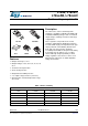
L78xx, L78xxC, L78xxAB, L78xxAC Positive voltage regulator ICs Datasheet - production data Description The L78xx series of three-terminal positive regulators is available in TO-220, TO-220FP, TO3, D²PAK and DPAK packages and several fixed output voltages, making it useful in a wide range of applications. TO-220 TO-3 These regulators can provide local on-card regulation, eliminating the distribution problems associated with single point regulation.
Contents L78xx, L78xxC, L78xxAB, L78xxAC Contents 1 Diagram . . . . . . . . . . . . . . . . . . . . . . . . . . . . . . . . . . . . . . . . . . . . . . . . . . . 5 2 Pin configuration . . . . . . . . . . . . . . . . . . . . . . . . . . . . . . . . . . . . . . . . . . . 6 3 Maximum ratings . . . . . . . . . . . . . . . . . . . . . . . . . . . . . . . . . . . . . . . . . . . . 7 4 Test circuits . . . . . . . . . . . . . . . . . . . . . . . . . . . . . . . . . . . . . . . . . . . . . . . .
L78xx, L78xxC, L78xxAB, L78xxAC List of tables List of tables Table 1. Table 2. Table 3. Table 4. Table 5. Table 6. Table 7. Table 8. Table 9. Table 10. Table 11. Table 12. Table 13. Table 14. Table 15. Table 16. Table 17. Table 18. Table 19. Table 20. Table 21. Table 22. Table 23. Table 24. Table 25. Table 26. Table 27. Table 28. Table 29. Table 30. Table 31. Table 32. Device summary . . . . . . . . . . . . . . . . . . . . . . . . . . . . . . . . . . . . . . . . . . . . . . . . . . . . . . . . . .
List of figures L78xx, L78xxC, L78xxAB, L78xxAC List of figures Figure 1. Figure 2. Figure 3. Figure 4. Figure 5. Figure 6. Figure 7. Figure 8. Figure 9. Figure 10. Figure 11. Figure 12. Figure 13. Figure 14. Figure 15. Figure 16. Figure 17. Figure 18. Figure 19. Figure 20. Figure 21. Figure 22. Figure 23. Figure 24. Figure 25. Figure 26. Figure 27. Figure 28. Figure 29. Figure 30. Figure 31. Figure 32. Figure 33. Figure 34. Figure 35. Figure 36. Figure 37. Figure 38. Figure 39. Figure 40. Figure 41.
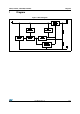
L78xx, L78xxC, L78xxAB, L78xxAC 1 Diagram Diagram Figure 1.
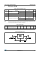
Pin configuration 2 L78xx, L78xxC, L78xxAB, L78xxAC Pin configuration Figure 2. Pin connections (top view) TO-220 D²PAK (Any Type) TO-220FP DPAK Figure 3.
L78xx, L78xxC, L78xxAB, L78xxAC 3 Maximum ratings Maximum ratings Table 2.
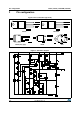
Test circuits 4 L78xx, L78xxC, L78xxAB, L78xxAC Test circuits Figure 5. DC parameter Figure 6. Load regulation Figure 7.
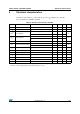
L78xx, L78xxC, L78xxAB, L78xxAC 5 Electrical characteristics Electrical characteristics Refer to the test circuits, TJ = -55 to 150 °C, VI = 10 V, IO = 500 mA, CI = 0.33 µF, CO = 0.1 µF unless otherwise specified. Table 4. Electrical characteristics of L7805 Symbol Parameter Test conditions Min. Typ. Max. Unit VO Output voltage TJ = 25°C 4.8 5 5.2 V VO Output voltage IO = 5 mA to 1 A, VI = 8 to 20 V 4.65 5 5.
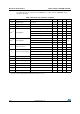
Electrical characteristics L78xx, L78xxC, L78xxAB, L78xxAC VI = 10 V, IO = 1 A, TJ = 0 to 125 °C (L7805AC), TJ = -40 to 125 °C (L7805AB), unless otherwise specified. Table 5. Electrical characteristics of L7805A Symbol Parameter Test conditions Min. Typ. Max. Unit VO Output voltage TJ = 25°C 4.9 5 5.1 V VO Output voltage IO = 5 mA to 1 A, VI = 7.5 to 18 V 4.8 5 5.2 V VO Output voltage IO = 1 A, VI = 18 to 20 V, TJ = 25°C 4.8 5 5.2 V VI = 7.
L78xx, L78xxC, L78xxAB, L78xxAC Electrical characteristics VI = 11 V, IO = 1 A, TJ = 0 to 125 °C (L7806AC), TJ = -40 to 125 °C (L7806AB), unless otherwise specified. Table 6. Electrical characteristics of L7806A Symbol Parameter Test conditions Min. Typ. Max. Unit VO Output voltage TJ = 25°C 5.88 6 6.12 V VO Output voltage IO = 5 mA to 1 A, VI = 8.6 to 19 V 5.76 6 6.24 V VO Output voltage IO = 1 A, VI = 19 to 21 V, TJ = 25°C 5.76 6 6.24 V VI = 8.
Electrical characteristics L78xx, L78xxC, L78xxAB, L78xxAC VI = 14 V, IO = 1 A, TJ = 0 to 125 °C (L7808AC), TJ = -40 to 125 °C (L7808AB), unless otherwise specified. Table 7. Electrical characteristics of L7808A Symbol Parameter Test conditions Min. Typ. Max. Unit VO Output voltage TJ = 25°C 7.84 8 8.16 V VO Output voltage IO = 5 mA to 1 A, VI = 10.6 to 21 V 7.7 8 8.3 V VO Output voltage IO = 1 A, VI = 21 to 23 V, TJ = 25°C 7.7 8 8.3 V VI = 10.
L78xx, L78xxC, L78xxAB, L78xxAC Electrical characteristics VI = 15 V, IO = 1 A, TJ = 0 to 125 °C (L7809AC), TJ = -40 to 125 °C (L7809AB), unless otherwise specified. Table 8. Electrical characteristics of L7809A Symbol Parameter Test conditions Min. Typ. Max. Unit VO Output voltage TJ = 25°C 8.82 9 9.18 V VO Output voltage IO = 5 mA to 1 A, VI = 10.6 to 22 V 8.65 9 9.35 V VO Output voltage IO = 1 A, VI = 22 to 24 V, TJ = 25°C 8.65 9 9.35 V VI = 10.
Electrical characteristics L78xx, L78xxC, L78xxAB, L78xxAC VI = 19 V, IO = 1 A, TJ = 0 to 125 °C (L7812AC), TJ = -40 to 125 °C (L7812AB), unless otherwise specified. Table 9. Electrical characteristics of L7812A Symbol Parameter Test conditions Min. Typ. Max. Unit VO Output voltage TJ = 25°C 11.75 12 12.25 V VO Output voltage IO = 5 mA to 1 A, VI = 14.8 to 25 V 11.5 12 12.5 V VO Output voltage IO = 1 A, VI = 25 to 27 V, TJ = 25°C 11.5 12 12.5 V VI = 14.
L78xx, L78xxC, L78xxAB, L78xxAC Electrical characteristics VI = 23 V, IO = 1 A, TJ = 0 to 125 °C (L7815AC), TJ = -40 to 125 °C (L7815AB), unless otherwise specified. Table 10. Electrical characteristics of L7815A Symbol Parameter Test conditions Min. Typ. Max. Unit VO Output voltage TJ = 25°C 14.7 15 15.3 V VO Output voltage IO = 5 mA to 1 A, VI = 17.9 to 28 V 14.4 15 15.6 V VO Output voltage IO = 1 A, VI = 28 to 30 V, TJ = 25°C 14.4 15 15.6 V VI = 17.
Electrical characteristics L78xx, L78xxC, L78xxAB, L78xxAC VI = 33 V, IO = 1 A, TJ = 0 to 125 °C (L7824AC), TJ = -40 to 125 °C (L7824AB), unless otherwise specified. Table 11. Electrical characteristics of L7824A Symbol Parameter Test conditions Min. Typ. Max. Unit 23.5 24 24.5 V VO Output voltage TJ = 25°C VO Output voltage IO = 5 mA to 1 A, VI = 27.
L78xx, L78xxC, L78xxAB, L78xxAC Electrical characteristics Refer to the test circuits, TJ = 0 to 125 °C, VI = 10 V, IO = 500 mA, CI = 0.33 µF, CO = 0.1 µF unless otherwise specified. Table 12. Electrical characteristics of L7805C Symbol Parameter Test conditions Min. Typ. Max. Unit VO Output voltage TJ = 25°C 4.8 5 5.2 V VO Output voltage IO = 5 mA to 1 A, VI = 7 to 18 V 4.75 5 5.25 V VO Output voltage IO = 1 A, VI = 18 to 20V, TJ = 25°C 4.75 5 5.
Electrical characteristics L78xx, L78xxC, L78xxAB, L78xxAC Refer to the test circuits, TJ = 0 to 125 °C, VI = 11 V, IO = 500 mA, CI = 0.33 µF, CO = 0.1 µF unless otherwise specified. Table 13. Electrical characteristics of L7806C Symbol Parameter Test conditions Min. Typ. Max. Unit VO Output voltage TJ = 25°C 5.75 6 6.25 V VO Output voltage IO = 5 mA to 1 A, VI = 8 to 19 V 5.7 6 6.3 V VO Output voltage IO = 1 A, VI = 19 to 21 V, TJ = 25°C 5.7 6 6.
L78xx, L78xxC, L78xxAB, L78xxAC Electrical characteristics Refer to the test circuits, TJ = 0 to 125 °C, VI = 14 V, IO = 500 mA, CI = 0.33 µF, CO = 0.1 µF unless otherwise specified. Table 14. Electrical characteristics of L7808C Symbol Parameter Test conditions Min. Typ. Max. Unit VO Output voltage TJ = 25°C 7.7 8 8.3 V VO Output voltage IO = 5 mA to 1 A, VI = 10.5 to 21 V 7.6 8 8.4 V VO Output voltage IO = 1 A, VI = 21 to 25 V, TJ = 25°C 7.6 8 8.
Electrical characteristics L78xx, L78xxC, L78xxAB, L78xxAC Refer to the test circuits, TJ = 0 to 125 °C, VI = 14.5 V, IO = 500 mA, CI = 0.33 µF, CO = 0.1 µF unless otherwise specified. Table 15. Electrical characteristics of L7885C Symbol Parameter Test conditions Min. Typ. Max. Unit VO Output voltage TJ = 25°C 8.2 8.5 8.8 V VO Output voltage IO = 5 mA to 1 A, VI = 11 to 21.5 V 8.1 8.5 8.9 V VO Output voltage IO = 1 A, VI = 21.5 to 26 V, TJ = 25°C 8.1 8.5 8.
L78xx, L78xxC, L78xxAB, L78xxAC Electrical characteristics Refer to the test circuits, TJ = 0 to 125 °C, VI = 15 V, IO = 500 mA, CI = 0.33 µF, CO = 0.1 µF unless otherwise specified. Table 16. Electrical characteristics of L7809C Symbol Parameter Test conditions Min. Typ. Max. Unit VO Output voltage TJ = 25°C 8.64 9 9.36 V VO Output voltage IO = 5 mA to 1 A, VI = 11.5 to 22 V 8.55 9 9.45 V VO Output voltage IO = 1 A, VI = 22 to 26 V, TJ = 25°C 8.55 9 9.
Electrical characteristics L78xx, L78xxC, L78xxAB, L78xxAC Refer to the test circuits, TJ = 0 to 125 °C, VI = 15 V, IO = 500 mA, CI = 0.33 µF, CO = 0.1 µF unless otherwise specified. Table 17. Electrical characteristics of L7810C Symbol Parameter Test conditions Min. Typ. Max. Unit VO Output voltage TJ = 25°C 9.6 10 10.4 V VO Output voltage IO = 5 mA to 1 A, VI = 12.5 to 23 V 9.5 10 10.5 V VO Output voltage IO = 1 A, VI = 23 to 26 V, TJ = 25°C 9.5 10 10.
L78xx, L78xxC, L78xxAB, L78xxAC Electrical characteristics Refer to the test circuits, TJ = 0 to 125 °C, VI = 19 V, IO = 500 mA, CI = 0.33 µF, CO = 0.1 µF unless otherwise specified. Table 18. Electrical characteristics of L7812C Symbol Parameter Test conditions Min. Typ. Max. Unit VO Output voltage TJ = 25°C 11.5 12 12.5 V VO Output voltage IO = 5 mA to 1 A, VI = 14.5 to 25 V 11.4 12 12.6 V VO Output voltage IO = 1 A, VI = 25 to 27 V, TJ = 25°C 11.4 12 12.
Electrical characteristics L78xx, L78xxC, L78xxAB, L78xxAC Refer to the test circuits, TJ = 0 to 125 °C, VI = 23 V, IO = 500 mA, CI = 0.33 µF, CO = 0.1 µF unless otherwise specified. Table 19. Electrical characteristics of L7815C Symbol Parameter Test conditions Min. Typ. Max. Unit VO Output voltage TJ = 25°C 14.4 15 15.6 V VO Output voltage IO = 5 mA to 1 A, VI = 17.5 to 28 V 14.25 15 15.75 V VO Output voltage IO = 1 A, VI = 28 to 30 V, TJ = 25°C 14.25 15 15.
L78xx, L78xxC, L78xxAB, L78xxAC Electrical characteristics Refer to the test circuits, TJ = 0 to 125 °C, VI = 26 V, IO = 500 mA, CI = 0.33 µF, CO = 0.1 µF unless otherwise specified. Table 20. Electrical characteristics of L7818C Symbol Parameter Test conditions Min. Typ. Max. Unit VO Output voltage TJ = 25°C 17.3 18 18.7 V VO Output voltage IO = 5 mA to 1 A, VI = 21 to 31 V 17.1 18 18.9 V VO Output voltage IO = 1 A, VI = 31 to 33 V, TJ = 25°C 17.1 18 18.
Electrical characteristics L78xx, L78xxC, L78xxAB, L78xxAC Refer to the test circuits, TJ = 0 to 125 °C, VI = 28 V, IO = 500 mA, CI = 0.33 µF, CO = 0.1 µF unless otherwise specified. Table 21. Electrical characteristics of L7820C Symbol Parameter Test conditions Min. Typ. Max. Unit 19.2 20 20.
L78xx, L78xxC, L78xxAB, L78xxAC Electrical characteristics Refer to the test circuits, TJ = 0 to 125 °C, VI = 33 V, IO = 500 mA, CI = 0.33 µF, CO = 0.1 µF unless otherwise specified. Table 22. Electrical characteristics of L7824C Symbol Parameter Test conditions Min. Typ. Max. Unit 23 24 25 V VO Output voltage TJ = 25°C VO Output voltage IO = 5 mA to 1 A, VI = 27 to 37 V 22.8 24 25.2 V VO Output voltage IO = 1 A, VI = 37 to 38 V, TJ = 25°C 22.8 24 25.
Application information L78xx, L78xxC, L78xxAB, L78xxAC 6 Application information 6.
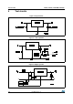
L78xx, L78xxC, L78xxAB, L78xxAC Application information Figure 9. Current regulator IO = VXX/R1+Id Figure 10. Circuit for increasing output voltage IR1 5 Id VO = VXX(1+R2/R1)+IdR2 Figure 11.
Application information L78xx, L78xxC, L78xxAB, L78xxAC Figure 12. 0.5 to 10 V regulator VO=VXXR4/R1 Figure 13. High current voltage regulator VBEQ1 R1 = ______________ IREQ-(IQ1/bQ1) VBEQ1 IO = IREG + Q1 (IREG ______) R1 Figure 14.
L78xx, L78xxC, L78xxAB, L78xxAC Application information Figure 15. Tracking voltage regulator Figure 16. Split power supply (± 15 V - 1 A) * Against potential latch-up problems.
Application information L78xx, L78xxC, L78xxAB, L78xxAC Figure 17. Negative output voltage circuit Figure 18. Switching regulator Figure 19.
L78xx, L78xxC, L78xxAB, L78xxAC Application information Figure 20. High input voltage circuit (configuration 2) Figure 21. High output voltage regulator Figure 22.
Application information L78xx, L78xxC, L78xxAB, L78xxAC Figure 23. Reducing power dissipation with dropping resistor VI(min)-VXX-VDROP(max) R = ____________________ IO(max)+Id(max) Figure 24. Remote shutdown Figure 25. Power AM modulator (unity voltage gain, IO 0.5) Note: 34/57 The circuit performs well up to 100 kHz.
L78xx, L78xxC, L78xxAB, L78xxAC Application information Figure 26. Adjustable output voltage with temperature compensation VO = VXX (1+R2/R1) + VBE Note: Q2 is connected as a diode in order to compensate the variation of the Q1 VBE with the temperature. C allows a slow rise time of the VO. Figure 27.
Application information L78xx, L78xxC, L78xxAB, L78xxAC Figure 28. Protection against input short-circuit with high capacitance loads Note: 36/57 Application with high capacitance loads and an output voltage greater than 6 volts need an external diode (see Figure 23 on page 34) to protect the device against input short circuit. In this case the input voltage falls rapidly while the output voltage decrease slowly.
L78xx, L78xxC, L78xxAB, L78xxAC 7 Typical performance Typical performance Figure 29. Dropout voltage vs. junction temperature Figure 30. Peak output current vs. input/output differential voltage Figure 31. Supply voltage rejection vs. frequency Figure 32. Output voltage vs. junction temperature Figure 33. Output impedance vs. frequency Figure 34. Quiescent current vs. junction temp.
Typical performance L78xx, L78xxC, L78xxAB, L78xxAC Figure 35. Load transient response Figure 36. Line transient response Figure 37. Quiescent current vs.
L78xx, L78xxC, L78xxAB, L78xxAC 8 Package mechanical data Package mechanical data In order to meet environmental requirements, ST offers these devices in different grades of ECOPACK® packages, depending on their level of environmental compliance. ECOPACK® specifications, grade definitions and product status are available at: www.st.com. ECOPACK® is an ST trademark. Table 23. TO-220 mechanical data Type STD - ST Dual Gauge Type STD - ST Single Gauge mm. mm. Dim. Min. Typ. Max. Min. Typ. Max.
Package mechanical data L78xx, L78xxC, L78xxAB, L78xxAC Figure 38. Drawing dimension TO-220 (type STD-ST Dual Gauge) 0015988_S Note: 40/57 1 Maximum resin gate protrusion: 0.5 mm. 2 Resin gate position is accepted in each of the two positions shown on the drawing, or their symmetrical.
L78xx, L78xxC, L78xxAB, L78xxAC Package mechanical data Figure 39.
Package mechanical data L78xx, L78xxC, L78xxAB, L78xxAC Figure 40. Drawing dimension tube for TO-220 Dual Gauge (mm.) Figure 41. Drawing dimension tube for TO-220 Single Gauge (mm.
L78xx, L78xxC, L78xxAB, L78xxAC Package mechanical data Figure 42.
Package mechanical data L78xx, L78xxC, L78xxAB, L78xxAC Table 24. TO-220FP mechanical data mm. inch. Dim. Min. Typ. Max. Min. Typ. Max. A 4.40 4.60 0.173 0.181 B 2.5 2.7 0.098 0.106 D 2.5 2.75 0.098 0.108 E 0.45 0.70 0.017 0.027 F 0.75 1 0.030 0.039 F1 1.15 1.50 0.045 0.059 F2 1.15 1.50 0.045 0.059 G 4.95 5.2 0.194 0.204 G1 2.4 2.7 0.094 0.106 H 10.0 10.40 0.393 0.409 L2 16 0.630 L3 28.6 30.6 1.126 1.204 L4 9.8 10.6 0.385 0.417 L5 2.
L78xx, L78xxC, L78xxAB, L78xxAC Package mechanical data Figure 43. Drawing dimension TO-3 D A P C O N B V U E G R P003C/C Table 25. TO-3 mechanical data mm. inch. Dim. Min. A B Typ. Max. Min. 11.85 0.96 1.05 Typ. Max. 0.466 1.10 0.037 0.041 0.043 C 1.70 0.066 D 8.7 0.342 E 20.0 0.787 G 10.9 0.429 N 16.9 0.665 P R 26.2 3.88 4.09 U V 1.031 0.152 0.161 39.5 30.10 1.555 1.
Package mechanical data L78xx, L78xxC, L78xxAB, L78xxAC Figure 44.
L78xx, L78xxC, L78xxAB, L78xxAC Package mechanical data Table 26. DPAK mechanical data mm. inch. Dim. Min. Typ. Max. Min. Typ. Max. A 2.2 2.4 0.086 0.094 A1 0.9 1.1 0.035 0.043 A2 0.03 0.23 0.001 0.009 B 0.64 0.9 0.025 0.035 b4 5.2 5.4 0.204 0.212 C 0.45 0.6 0.017 0.023 C2 0.48 0.6 0.019 0.023 D 6 6.2 0.236 0.244 D1 E 5.1 6.4 0.200 6.6 0.252 0.260 E1 4.7 0.185 e 2.28 0.090 e1 4.4 4.6 0.173 0.181 H 9.35 10.1 0.368 0.397 L 1 0.
Package mechanical data L78xx, L78xxC, L78xxAB, L78xxAC Figure 45. Drawing dimension tape and reel for DPAK Table 27. Tape and reel DPAK mechanical data mm. inch. Dim. Min. Typ. A Min. Typ. 330 13.0 13.2 Max. 12.992 C 12.8 D 20.2 0.795 N 60 2.362 T 48/57 Max. 0.504 0.512 22.4 0.519 0.882 Ao 6.80 6.90 7.00 0.268 0.272 0.2.76 Bo 10.40 10.50 10.60 0.409 0.413 0.417 Ko 2.55 2.65 2.75 0.100 0.104 0.105 Po 3.9 4.0 4.1 0.153 0.157 0.161 P 7.9 8.0 8.1 0.
L78xx, L78xxC, L78xxAB, L78xxAC Package mechanical data Figure 46.
Package mechanical data L78xx, L78xxC, L78xxAB, L78xxAC Figure 47. Drawing dimension D²PAK (type WOOSEOK-Subcon.
L78xx, L78xxC, L78xxAB, L78xxAC Package mechanical data Table 28. D²PAK mechanical data Dim. Min. Type WOOSEOK-Subcon. mm. mm. Typ. Max. Min. Typ. Max. A 4.40 4.60 4.30 4.70 A1 0.03 0.23 0 0.20 b 0.70 0.93 0.70 0.90 b2 1.14 1.70 1.17 1.37 c 0.45 0.60 0.45 0.50 0.60 c2 1.23 1.36 1.25 1.30 1.40 D 8.95 9.35 9 9.20 9.40 D1 7.50 E 10 E1 8.50 e 7.50 10.40 9.80 10.20 7.50 2.54 2.54 e1 4.88 5.28 H 15 15.85 15 J1 2.49 2.69 2.20 2.60 L 2.
Package mechanical data L78xx, L78xxC, L78xxAB, L78xxAC Figure 48. D²PAK footprint recommended data Table 29. D²PAK footprint data Values 52/57 Dim. mm. inch. A 12.20 0.480 B 9.75 0.384 C 16.90 0.665 D 3.50 0.138 E 1.60 0.063 F 2.54 0.100 G 5.08 0.
L78xx, L78xxC, L78xxAB, L78xxAC Package mechanical data Table 30. Tape and reel D²PAK mechanical data mm. inch. Dim. Min. Typ. A Max. Min. Typ. 180 13.0 7.086 C 12.8 D 20.2 0.795 N 60 2.362 T 13.2 Max. 0.504 0.512 14.4 0.519 0.567 Ao 10.50 10.6 10.70 0.413 0.417 0.421 Bo 15.70 15.80 15.90 0.618 0.622 0.626 Ko 4.80 4.90 5.00 0.189 0.193 0.197 Po 3.9 4.0 4.1 0.153 0.157 0.161 P 11.9 12.0 12.1 0.468 0.472 0.476 Figure 49.
Order codes 9 L78xx, L78xxC, L78xxAB, L78xxAC Order codes Table 31.
L78xx, L78xxC, L78xxAB, L78xxAC Order codes Table 31.
Revision history 10 L78xx, L78xxC, L78xxAB, L78xxAC Revision history Table 32. Document revision history Date Revision 21-Jun-2004 12 Document updating. 03-Aug-2006 13 Order codes has been updated and new template. 19-Jan-2007 14 D²PAK mechanical data has been updated and add footprint data. 31-May-2007 15 Order codes has been updated. 29-Aug-2007 16 Added Table 1 in cover page. 11-Dec-2007 17 Modified: Table 31.
L78xx, L78xxC, L78xxAB, L78xxAC Please Read Carefully: Information in this document is provided solely in connection with ST products. STMicroelectronics NV and its subsidiaries (“ST”) reserve the right to make changes, corrections, modifications or improvements, to this document, and the products and services described herein at any time, without notice. All ST products are sold pursuant to ST’s terms and conditions of sale.