Model U421/U444 (Serial #17978 and up) OWNER'S MANUAL Manual No. 513595-4 July, 2004 Rev.
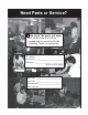
Need Parts or Service? We stock the parts you need. Our Technicians are factory trained and are certified in the Stoelting Technicare program. CALL Distributor: _________________________ Phone No.: _________________________ (fill in or affix label) Model No.: _______________________ Serial No.
STOELTING® OWNER'S MANUAL FOR MODEL U421/U444 CAB MODEL SOFT-SERVE PRESSURIZED FREEZER This manual provides basic information about the freezer. Instructions and suggestions are given covering its basic operation and care. The illustrations and specifications are not binding in detail. We reserve the right to make changes at any time without notice, to the freezer and its components, without incurring any obligation to modify or provide new parts for freezers built prior to date of change.
TABLE OF CONTENTS Section 1 .............................................................................................................. 1 1.1 1.2 Description .............................................................................................. 1 Specifications.......................................................................................... 2 Section 2 .............................................................................................................. 3 2.1 2.2 2.3 2.4 2.
ILLUSTRATIONS Figure 1 Model U421/U444 Series Freezer .........................................1 Figure 2a Air-Cooled Specifications ......................................................2 Figure 2b Water-Cooled Specifications .................................................2 Figure 3 Decal Locations .....................................................................3 Figure 4 Water/Electrical Connections .................................................4 Figure 5 Auger Rotation ..................
A Few Words About Safety Safety Information Read and understand the entire manual before operating or maintaining Stoelting equipment. This Owner's Manual provides the operator with information for the safe operation and maintenance of Stoelting equipment. As with any machine, there are hazards associated with their operation. For this reason safety is emphasized throughout the manual. To highlight specific safety information, the following safety definitions are provided to assist the reader.
SECTION 1 INTRODUCTION 1.1 DESCRIPTION The Stoelting U421 and U444 floor model freezers are pressure fed. The freezers are equipped with fully automatic controls to provide a uniform product. The U421 freezer is designed to operate with almost any type of commercial soft serve or non-dairy mixes available, including ice milk, ice cream, yogurt, and frozen dietary desserts. The U444 freezer is designed to dispense soft serve product from the right side and shake product from the left side.
Figure 2a. Air-Cooled Specification Figure 2b.
SECTION 2 INSTALLATION INSTRUCTIONS 2.1 SAFETY PRECAUTIONS Do not attempt to operate the freezer until the safety precautions and operating instructions in this manual are read completely and are thoroughly understood. If danger, warning or caution labels are needed, indicate the part number, type of label, location of label, and quantity required along with your address and mail to: Take notice of all warning labels on the freezer.
2.2 SHIPMENT AND TRANSIT The freezer has been assembled, operated, and inspected at the factory. Upon arrival at the final destination, the freezer must be checked for any damage which may have occurred during final transit. D. The freezer must have a minimum of 3" (7,5cm) -6" (15cm) high ambient conditions- of space on all sides and 10" (25cm) at the top for proper circulation. CAUTION With the method of packaging used, the equipment should arrive in excellent condition.
Auger shaft rotation is clockwise as viewed through the clear plastic front door. If the rotation is not clockwise, turn main electrical power OFF. Then reverse L1 and L3 electrical power lines to the junction box (three phase only). Re-check auger shaft rotation. Figure 5. A. Refer to the nameplate at the rear of the freezer for specific electrical requirements. Make sure the power source in the building matches the freezer nameplate requirements.
5.Turn pump off. B. Connect 1/2 inch (12,7mm) I.D. plastic food grade tubing to check valve and then to the mix container. Observe check valve flow arrow. Secure with hose clamps. Then place assembly thru hole in cover and install retainer clip. Figure 9. C. Connect 1/2 inch (12,7mm) I.D. plastic food grade tubing between the large port of air/mix tee and refrigerated mix transfer line. Secure with large hose clamp or equivalent. Figure 9. 6.
Å Refrigerated Mix Transfer Line Large PortÆ (Air/Mix) Å 3-way Tee Figure 8. 3-way Tee Low Mix Cord Ì Cover È Mix Container É Retainer Clip Figure 9. Mix Inlet Tube & Probe Assy. Clip Ç Hose Holder Figure 10.
8
SECTION 3 INITIAL SET-UP AND OPERATION 3.2 OPERATING CONTROLS AND INDICATORS Before operating the freezer, it is required that the operator know the function of each operating control. Refer to Fig.11 for the location of the operating controls on the freezer. 3.1 SAFETY PRECAUTIONS SAFE OPERATION IS NO ACCIDENT; observe these rules: A. Know the freezer. Read and understand the operating instructions. B. Notice all warning labels on the freezer. C. Wear proper clothing.
When the switch is placed in the OFF position, the refrigeration system and auger will not operate. When the switch is placed in the SERVE position, the refrigeration system and auger will operate automatically. The switch should be placed in the SERVE position for normal operation. C. Cabinet-Off-On Switch The CABINET-OFF-ON switch is a two position toggle switch. When the switch is placed in the OFF position, the lower cabinet refrigeration system will not run.
CLEANING · Is the removal of soil materials from a surface. · Is a prerequisite for effective sanitizing. 3.3 IMPORTANT INFORMATION REGARDING CLEANING AND SANITIZING Soft serve and shake freezers require special consideration when it comes to food safety and proper cleaning and sanitizing. NOTE An UNCLEAN surface will harbor bacteria that can defy sanitizing efforts. The following information specifically covers issues for cleaning and sanitizing frozen dessert freezers.
The ideal concentration of chlorine needs to be 100 ppm (as stated by the FDA). As a recommended cleaner and sanitizer for your frozen dessert machine, STERA-SHEEN has proven to be one of the best daily maintenance products for: · CLEANING – Thorough removal of all solids including butterfat and milk fat. NOTE Follow the directions on the container for proper concentration. · MILKSTONE REMOVAL – Complete removal of milkstone.
A. Disassembly Of Front Door 1. Remove the front door by turning off the black knobs and then pulling the front door off the studs. 2. Remove the air bleed valve by unscrewing the knob while holding the valve stem from behind. Remove the compression spring and push air bleed valve through the rear of the front door. 3. Remove the spigot through the bottom of the front door (see Figure 13). Remove all O-rings from spigot and air bleed valve. Figure 15. Rear Seal Removal 3.
3.7 CLEANING THE FREEZER É CAUTION Lubricate with Socket Lubricant Risk of Product Damage Do not use acid cleaners, strong caustic compounds or abrasive materials to clean any part of the freezer exterior or plastic parts. É Ê É Lubricate with Petrogel Figure 16. Rear Seal Lubrciation The exterior should be kept clean at all times to preserve the lustre of the stainless steel. A good grade of stainless steel has been used on the freezer to ease clean-up.
G. Assemble O-rings onto the spigot dry, without lubrication. Then apply a thin film of sanitary lubricant to the outside of the O-rings and spigot bodies. H. Install the spigot through the bottom of the front door ( see Figure 18). Figure 18. Front Door Assembly I. Assemble the air bleed valve O-ring onto the air bleed valves. Position the O-ring in groove close to the wide part. Apply a thin film of sanitary lubricant to the O-rings. J. Insert the air bleed valve from the back of the front door.
3.9 SANITIZING Sanitizing must be done after the freezer is clean and just before the freezer is filled with mix. Sanitizing the night before is not effective. However, you should always clean the freezer and parts after using it. C. Let sanitizing solution fill the freezer barrel to air bleed valve, then close the valve by pulling out to lock in place. D. Place the CLEAN-OFF-SERVE toggle switch in the ON position while pressing the CLEAN switch.
The freezer is designed to dispense the product at a reasonable draw rate. If the freezer is overdrawn, the result will be a soft product and air pops. If this should occur, allow the freezer to run for approximately 30 seconds before dispensing additional product. After a while the operator will sense or feel when the freezer is beginning to fall behind, and will slow down on the rate of draw so as not to exceed the freezer's capacity.
C. 3.12 OPERATION OF MIX PUMP The pump switch is located on the front of the freezer. When the pump switch is placed in the ON position, the mix pump motor will be actuated to pump mix into the freezer cylinder. When the set pressure is reached, the mix pump will shut off automatically. When the switch is placed in the OFF position, the mix pump will be inoperative. NOTICE Any cleaning procedure must always be followed by sanitizing before filling freezer with mix. (Refer to section 3.3) 3.
NOTE If the mix lines or air line is difficult to remove, soften with a rag soaked in hot water. Hose connections may be sprayed with Haynes Sanitary Lubricant for ease of removal. Do not loosen or remove the mix pump cover wingnuts. Maintain the mix pump hose in its operational condition. 9. Sanitize assembled freezer as per instructions outlined in Section 3.9). 1. Loosen clamp and remove air hose from pump compressor. 2. Loosen clamp and disconnect mix pump hose.
20
SECTION 4 MAINTENANCE INSTRUCTIONS The mix pump that fills the left freezing cylinder of the U444 has been preset at the factory to produce a soft serve product with approximately 40% overrun. The mix pump that fills the right freezing cylinder of the U444 has been preset at the factory to produce a shake product with approximately 50% overrun. The left and right pumps on the U421 have been preset to produce a soft serve product with approximately 40% overrun.
F. Tighten the allen screw, then place the wrench back in its clip. Replace the lower back panel and secure with the four screws. Turn the mix pump power switch to the ON position. CAUTION UTION Never disconnect hoses from freezer or pump without first opening spigot to relieve pressure. 4.4. MIX PUMP HOSE REPOSITION (every one or two weeks.) 3. Disconnect mix pump hose at each end. NOTICE Mix pump hose must be repositioned every 1 - 2 weeks.
A. Remove either side and back panels. B. Press firmly on one belt. Figure 29. NOTICE If the condenser is not kept clean, loss of refrigeration efficiency will result. 4.9 PREVENTATIVE MAINTENANCE It is recommended that a preventative maintenance schedule be followed to keep the freezer clean and operating properly. The following steps are suggested as a preventative maintenance guide.
D. For water-cooled freezers that are left in unheated buildings, or buildings subject to freezing, the water must be shut off and disconnected. Disconnect fittings at water valve inlet and water outlet lines at the freezer. The fittings are located at the rear of the freezer. Run the compressor for 2 - 3 minutes to open water valve. Blow out all water, first through water inlet, then through water outlet lines with air or carbon dioxide. Also drain water supply line to the freezer. E.
FREEZER PROBLEM Drive motor (auger) "kicks-out", or does not run. FREEZER POSSIBLE CAUSE 1. Power to freezer is off. 2. Drive motor overloaded. 3. Low line voltage. 4. Product too hard. 5. Front door not installed securely. REMEDY 1. Check power to freezer. 2. Wait 15-20 min. for Thermo overload to reset. 3. Check, must be +\-10% of nameplate voltage. 4. Raise overrun and/or product temperature. (See Section 4.3 or 4.2) 5. Install front door securely. 4. Compressor internal overload is cut-out. 5.
MIX PUMP 1. PU MP MOTOR D OES N OT R U N Power to pump i s off. Supply power to pump. Low voltage. C heck for low li ne voltage. Mi x pump hose jammed i nsi de black cover/clamp. D i sconnect pump from power source. Remove four cover/clamp thumb screws. Separate cover/clamp halves and remove outer half. Remove jammed hose. Re-i nstall cover/clamp and ti ghten four thumb screws securely. Allow motor thermal overload to reset. See Sec. 2.5 for hose replacement. D o not use jammed porti on of hose.
5. REPLACEMENT MIX PUMP HOSE WON'T FEED THROUGH PUMP Feeding hose into discharge hole of mix pump cover. Feed hose into pick-up side of cover. Hose ends not cut squarely. Carefully cut hose end off squarely (no tails). Force feeding too quickly. Gently and slowly assist feeding of hose up into pick-up hose side of cover. Pump motor not running. Turn on motor switch. Also see Item 1 above. 6. AIR EXITING MIX PICK-UP HOSE Pickup tube check valve missing. Contact local Stoelting Distributor. 7.
28
SECTION 5 HOW TO ORDER REPLACEMENT PARTS 5.1 HOW TO ORDER REPLACEMENT PARTS To assure the receipt of the proper replacement parts, supply your Authorized Stoelting Distributor with the following information: A. Model number of equipment. B. Serial number of model (stamped on nameplate) C. Part number, part name, and quantity needed. NOTICE Minimum billing is $50.00 Net. 5.2 PARTS LIST AND REFERENCE DRAWINGS The following lists and drawings will aid the user when ordering parts or servicing.
FRONT DOOR PARTS Drawing Index No. 7 11 12 13 14 15 16 17 18 19 20 21 22 23 Part No. Description 625133 624520 694200 482004 2110116 1107123 570998 2146293 2157892 2143024 624655 624645 3152581 624677 1177905 482035 O-ring, Front Door O-ring, Air Bleed Valve Spring, Air Bleed Valve Knob, Air Bleed, Black Stem, Air Bleed Valve Spigot Handle Retaining Pin Spigot Extension, 2.1 Spigot Extension, 1.5 Spigot Extension, 3.
AUGER PARTS Drawing Index No. 1 2 3 4 5 6 7 8 Part Number Qty. Description 2104552 149003 381804 694255 4151178 624678 1151859 667868 1 1 6 6 1 1 1 1 Auger Front Support Front Bearing Plastic Flight Spring Auger Rear Seal O-ring Rear Seal Adaptor Rear Seal MISCELLANEOUS PARTS Description Part No. Haynes Spray 12 oz.(340 grams) -------------------- 508017 Petro-Gel Tube 4 oz. (113 grams) -------------------- 508135 Spline Lubricant 2 oz.
Figure 7.
DECALS Qty. Part Number Description 2 2 2 1 2 1 1 2 4 1 2 324200 324798 324797 324800 324799 324141 324509 324014 324686 723525 324106 2 3 2 2 1 2 1 1 2 2 3 1 2 2 2 2 1 1 1 1 324346 324107 324208 723552 723517 H.P. Manual Reset Clean-Off-Serve Standby/Serve Cab Off-On Pump Off On Caution, Haz. Rot. Blade - Front Panel Cleaning - Right Side Auger Rotation - Evap. Enclosure Rear Danger - Start Auto, on Evap. Support between belts & motors support brkt.
34
GENERAL ORDER ADVICE Customer No.: ________________ Customer P.O. No.: ________________ Stoelting Order No.
36
GENERAL ORDER ADVICE Customer No.: ________________ Customer P.O. No.: ________________ Stoelting Order No.
WARRANTY SOFT SERVE / SHAKE FREEZERS 1.