StorCase® Technology InfoStation® 12-Bay SCSI Ultra320 External Expansion Chassis Installation Guide
i StorCase® Technology InfoStation® 12-Bay SCSI Ultra320 External Expansion Chassis Installation Guide Part No. D89-0000-0216 A02 March 2004 StorCase Technology, Inc. 17600 Newhope Street Fountain Valley, CA 92708-9885 Phone (714) 438-1850 Fax (714) 438-1847 InfoStation 12-Bay Installation Guide - Rev. A02 StorCase Technology, Inc.
ii Important Safety Instructions 1. Read all these instructions. 2. Save these instructions for later use. 3. Follow all warnings and instructions marked on the product. 4. Do not use this product near water. 5. This product should be operated from the type of power source indicated on the marking label. If you are not sure of the type of power available, consult your dealer or local power company. 6.
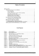
iii Table of Contents INSTALLATION ...................................................................................................................... 1 Installing the Drive(s) into the InfoStation ................................................................... 1 Drive Preparation .................................................................................................. 1 Carrier Preparation ...............................................................................................
iv NOTICE: This User's Guide is subject to periodic updates without notice. While reasonable efforts have been made to ensure accuracy of this document, StorCase Technology, Inc. assumes no liability resulting from errors or omissions in this publication, or from the use of the information contained herein. Please check the StorCase web site at http://www.storcase.com or contact your StorCase representative for the latest revision of this document. StorCase Technology, Inc.
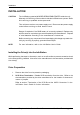
Installation 1 INSTALLATION CAUTION: The InfoStation contains NO USER SERVICEABLE PARTS inside the unit. Warranty is VOID if any of the modules inside the InfoStation are opened. Refer ALL servicing to qualified service personnel! This unit has more than one power supply cord. Disconnect two power supply cords before servicing to avoid electric shock. Danger of explosion if the RAID battery is incorrectly replaced! Replace only with the same or equivalent type recommended by the manufacturer.
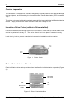
2 Installation Carrier Preparation The InfoStation is shipped in a container designed to provide protection and prevent damage during shipment, as confirmed by the International Safe Transit Association (ISTA Procedure 1A). The drive carriers are individually packed in a special foam insert within the InfoStation shipping carton. Simply remove them from the foam insert when ready for use. Inserting a Drive Carrier (without a Drive Installed) Lift carrier handle while inserting drive carrier into chassis.
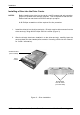
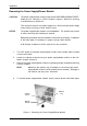
Installation 3 Installing a Drive into the Drive Carrier NOTES: Before installing the drive into the carrier, the ID jumpers and spin-up option jumper on the disk drive must be removed. This is required so that the InfoStation itself can set the drive SCSI ID and spin-up option. A #2 Phillips screwdriver will be required for this procedure. 1. Install the drive(s) into the drive carrier(s). Drive(s) must be side-mounted into the drive carrier(s) using #6-32 Phillips Pan Hd. screws (Figure 3). 2.
4 Installation Inserting a Drive into the Chassis NOTES: A new drive can be inserted into an empty bay at anytime. However, the drive will not be ready for access until the following procedure is followed. The key lock is only to prevent unauthorized removal or installation of the drive carrier. Locking the key lock is not required for drive carrier operation. 1. Drive is ready to be accessed when the Drive Ready LED glows.
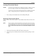
Installation 5 Removing the Power Supply/Blower Module CAUTION: The power supply/blower module contains NO USER SERVICEABLE PARTS inside the unit. Warranty is VOID if module is opened. Refer ALL servicing to qualified service personnel! This unit has more than one power supply cord. Disconnect two power supply cords before servicing to avoid electric shock. NOTES: The power supply/blower module is hot-swappable. The chassis may remain on when removing and installing the module.
6 Installation Installing the Power Cord Retainer Clip CAUTION: The power supply/blower module contains NO USER SERVICEABLE PARTS inside the unit. Warranty is VOID if module is opened. Refer ALL servicing to qualified service personnel! This unit has more than one power supply cord. Disconnect two power supply cords before servicing to avoid electric shock. 1. Turn OFF power to the power supply/blower module via the power switch located on the module itself.
Installation 7 1 2 IFS12_9 Retainer Clip Power Cord Figure 6: Installing the Power Cord Retainer Clip NOTE: When removing the power supply/blower module, make sure the retainer clip (if installed) is not blocking the power supply/blower module handle (handle pivots outward). Damage to the retainer clip may occur otherwise. InfoStation 12-Bay Installation Guide - Rev. A02 StorCase Technology, Inc.
8 Installation Removing and Installing the I/O Module (Procedure and information below applies to both the I/O Module and I/O Repeater Module) CAUTION: Remove ALL power from the InfoStation before removing the I/O module. The I/O module contains NO USER SERVICEABLE PARTS inside the unit. Refer ALL servicing to qualified service personnel! VHDCI connectors are easily damaged by improper handling. Visually inspect each connector for bent contacts and carefully align prior to insertion.
Installation 9 Removing the Chassis Access Panel CAUTION: Remove ALL power from the InfoStation before removing the access panel(s). The InfoStation contains NO USER SERVICEABLE PARTS inside the unit. Warranty is VOID if any of the modules inside the InfoStation are opened. Refer ALL servicing to qualified service personnel! NOTE: A #2 Phillips screwdriver will be required for this procedure. 1. Unplug the InfoStation and verify that ALL cables have been disconnected. 2.
10 Installation Installing a Half-Height or Full-Height 5.25" SCSI Device (such as a Canister-Type Device) CAUTION: Remove ALL power from the InfoStation before removing the access panel(s). The InfoStation contains NO USER SERVICEABLE PARTS inside the unit. Warranty is VOID if any of the modules inside the InfoStation are opened. Refer ALL servicing to qualified service personnel! This unit has more than one power supply cord. Disconnect two power supply cords before servicing to avoid electric shock.
Installation 7. 11 Carefully remove the I/O Panel (located in the rear of the chassis) by loosening the two (2) Captive Screws (Figure 10). I/O Panel Captive Screw (2 Total) IFS12_19 Figure 10: Removing the I/O Panel 8. Once I/O panel is removed, loosen and remove the two (2) #6-32 Phiilips Flat Hd. screws securing the I/O Blank Plate to the I/O Panel (Figure 11). Remove the appropriate I/O Blank Plate necessary to accommodate your particular SCSI cabling configuration.
12 Installation 9. Install the provided I/O Cut-Out Plate (Figure 9) onto your SCSI Cables. NOTES: The I/O Cut-Out Plate can be found inside the InfoStation accessory packet. SCSI cables are not included.
Installation 13 10. Install the I/O Plates onto the I/O Panel using the same screws saved from Step 8. 11. Install cables onto the SCSI device and carefully reinstall the I/O Panel back onto the rear of the InfoStation chassis. Make sure that none of the cables are pinched when reinstalling the I/O Panel back onto the chassis. 12. If desired, affix labels (Figure 14A) onto the I/O Panel to help identify the I/Os (Figure 14B).
14 Installation Installing the RAID Battery Backup Unit(s) into the InfoStation CAUTION: Remove ALL power from the InfoStation before installing the RAID Battery Backup Unit(s). Refer ALL servicing to qualified service personnel! Danger of explosion if the RAID battery is incorrectly replaced! Replace only with the same or equivalent type recommended by the manufacturer. Dispose of used batteries according to the manufacturer's instructions.
Installation 15 Blank Plate #6-32 Phillips F. H. Screw Power Supply/Blower Module IFS12_14 Figure 16: Installation Location of RAID Battery Backup Unit Battery Module IFS12_16 Power Supply/Blower Module Figure 17: Installing the RAID Battery Backup Unit into the Power Supply/Blower Module InfoStation 12-Bay Installation Guide - Rev. A02 StorCase Technology, Inc.
16 Installation Installing a Non-StorCase RAID Battery into the InfoStation CAUTION: Remove ALL power from the InfoStation before installing any Non-StorCase RAID Battery. Refer ALL servicing to qualified service personnel! Danger of explosion if the RAID battery is incorrectly replaced! Replace only with the same or equivalent type recommended by the manufacturer. Dispose of used batteries according to the manufacturer's instructions. NOTES: Please refer to RAID manufacturer's battery specifications.
Installation 17 I/O Panel Inside chassis with access cover removed Insert bracket tab here Fasten thumbscrews here Figure 19: Installation Location for RAID Battery/Bracket Assembly InfoStation 12-Bay Installation Guide - Rev. A02 StorCase Technology, Inc.