
Owner's manual

vi
StorCase Technology, Inc. SATA DE110 User's Guide - Rev. A03
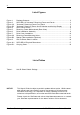
List of Figures
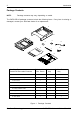
Figure 1: Package Contents .............................................................................................. 2
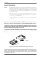
Figure 2: SATA DE110 "Universal" Receiving Frame and Carrier................................... 3
Figure 3A: "Universal" Receiving Frame Front Panel ......................................................... 5
Figure 3B: "Universal" Receiving Frame Unit ID Number and Activity Display ................. 5
Figure 4: SATA Drive Carrier ............................................................................................ 6
Figure 5: Receiving Frame Motherboard (Rear View) ..................................................... 7
Figure 6: Drive Installation Assembly ................................................................................ 8
Figure 7: Drive Cover Installation .................................................................................... 10
Figure 8A: Receiving Frame Mounting Holes .................................................................... 11
Figure 8B: Spacer Plate Installation (Optional) ................................................................. 12
Figure 9: Unit ID Select Switch Location ........................................................................ 14
Figure A-1: SATA DE110 Physical Dimensions.................................................................. 17
Figure B-1: Carrying Case ................................................................................................... 18
NOTICE: This User's Guide is subject to periodic updates without notice. While reason-
able efforts have been made to ensure the accuracy of this document,
StorCase Technology, Inc. assumes no liability resulting from errors or
omissions in this publication, or from the use of the information contained herein.
Please check the StorCase web site at http://www.storcase.com or contact
your StorCase representative for the latest revision of this document.
List of Tables
Table 1: Unit ID Select Switch Settings ......................................................................... 14