Clarendon & Ashdon Log Effect Stove Range Balanced Flue With upgradeable control valve Instructions for Use, Installation and Servicing For use in GB, IE (Great Britain and Eire) This appliance has been certified for use in countries other than those stated. To install this appliance in these countries, it is essential to obtain the translated instructions and in some cases the appliance will require modification. Contact Gazco for further information.
CONTENTS COVERING THE FOLLOWING MODELS ASHDON - 8546LUC - P8546LUC / 8544LUC - P8544LUC CLARENDON 8545LUC - P8545LUC / 8547LUC - P8547LUC PAGE APPLIANCE COMMISIONING CHECKLIST 3 USER INSTRUCTIONS 4 INSTALLATION INSTRUCTIONS 8 Technical Specifications 8 Site Requirements 9 Installation 13 Commissioning 19 SERVICING INSTRUCTIONS 20 Servicing Requirements 20 Fault Finding 20 How to replace parts 22 Basic spare parts list 25 Service Record 26 2
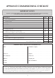
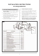
APPLIANCE COMMISSIONING CHECKLIST IMPORTANT NOTICE Explain the operation of the appliance to the end user, hand the completed instructions to them for safe keeping, as the information will be required when making any guaranteed claims. FLUE CHECK PASS 1. Flue is correct for appliance 2. Flue flow test N/A 3. Spillage test N/A FAIL GAS CHECK 1. Gas soundness & let by test 2. Standing pressure test mb 3.
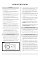
USER INSTRUCTIONS 2.4 2.5 1. GENERAL 1.1 Installation and servicing must be carried out by a competent person. 1.2 In all correspondence, please quote the appliance type and serial number which can be found on the data badge located at the rear of the stove. 1.3 Ensure curtains are not positioned above the stove, and that there is at least a clearance of 300mm between the sides of the stove and any curtains. 1.
USER INSTRUCTIONS 2 5. HANDLING & DISPOSAL OF FIRE CERAMICS 5.1 5.2 5.3 5.4 5.5 The fuel effect and side panels in this appliance are made from Refractory Ceramic Fibre (RCF), a material which is commonly used for this application. Protective clothing is not required when handling these articles, but we recommend you follow normal hygiene rules of not smoking, eating or drinking in the work area and always wash your hands before eating or drinking.
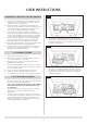
USER INSTRUCTIONS 7.4 Place log D across from the rear log A to log B on the lefthand side. There are cut-outs in both logs for location. See diagram 5. 8 5 AR1616 7.8 Carefully insert the front coal retainer into the front panel of the firebox. Take care not the scrape/damage the logs. This coal retainer sits in two brackets. Ensure it is fully inserted, leaving approximately a 4 mm gap between the firebox ledge and the bottom of the coal retainer. AR1613 7.
USER INSTRUCTIONS 8. THE FLAME FAILURE DEVICE 8.1 This is a safety feature incorporated in all GAZCO fires which automatically switches off the gas supply if the pilot light goes out and fails to heat the thermocouple. 9. ‘RUNNING IN’ 9.1 The surface coating on your GAZCO fires will "burn off" during the first 24 hour of use, producing a harmless and temporary odour. This will disappear after the short period of use. If the odour persists, ask your installer for advice. 10. SERVICING 10.
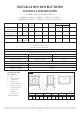
INSTALLATION INSTRUCTIONS TECHNICAL SPECIFICATION COVERING THE FOLLOWING MODELS: ASHDON - 8546LUC - P8546LUC / 8544LUC - P8544LUC CLARENDON - 8545LUC - P8545LUC / 8547LUC - P8547LUC Model Gas Gas Working Aeration Injector Input kW (Gross) 3/h CAT. Type Pressure 8545LUC-8547LUC 8546LUC-8544LUC I2H Natural (G20) 20 mbar Ø 1 x 14.5 375 P8545LUC-P8547LUC P8546LUC-P8547LUC I3P Propane (G31) 37 mbar Ø 2 x 12 165 Rear Exit Flue Gas Rate Country High Low 0.600 6.4 3.6 GB, IE 0.
INSTALLATION INSTRUCTIONS SITE REQUIREMENTS 1.1 TIMBER FRAMED BUILDINGS 1. FLUE AND CHIMNEY REQUIREMENTS 1.5 NOTE: This appliance can only be installed in conjunction with the flue supplied. The flue must be sited in accordance with BS5440: Part 1 (latest editon). See diagram 1. Any terminal which is less than 2 metres above any access (level ground, balcony or above a flat roof to which people have access), is to be fitted with the guard.
INSTALLATION INSTRUCTIONS SITE REQUIREMENTS 1.4 TOP FLUE UP & OUT KIT (8523/8523AN) 1.2 REAR FLUE 8526 Vertical from the top of the appliance then horizontally out. (See diagram 3.) Terminal dimensions: 395 x 200 x 200 mm (H x W x D) The basic kit comprises: 1 x 500mm vertical length 1 x 500mm terminal length (cut to length on site) 1 x 90 degree elbow 1 x wall plate 1 x 75mm restrictor fixing screws Cut to length as required on site. 2 The kit is the minimum required.
INSTALLATION INSTRUCTIONS SITE REQUIREMENTS 1.5 TOP FLUE UP & OUT WITH ADDITIONAL BEND Extra lengths may be added (see section 1.5), with reference to diagram 4 and the installation instructions of the appliance. Refer to Table A under 3.3, Installation to identify when to use each restrictor. Any additional bend may be used on the horizontal section (either 45° or 90°) but the overall horizontal flue run will be reduced. Refer to diagram 4. 1.
INSTALLATION INSTRUCTIONS SITE REQUIREMENTS 4.4 2. VENTILATION The appliance requires no additional ventilation. The above dimensions provide adequate clearance at the side and rear of the fire so that the controls can be rached and a spillage test performed where applicable. 7 3. INSTALLATION OF THE GAS SUPPLY 3.1 Before installation, ensure that the local distribution conditions (identification of the type of gas and pressure) and the adjustment of the appliance are compatible.
INSTALLATION INSTRUCTIONS INSTALLATION IMPORTANT: ENSURE THAT THE APPLIANCE IS CORRECTLY ADJUSTED FOR THE GAS TYPE AND CATEGORY APPLICABLE IN THE COUNTRY OF USE. REFER TO DATABADGE AND TECHNICAL SPECIFICATIONS OF THIS BOOKLET. FOR DETAILS OF CHANGING BETWEEN GAS TYPES REFER TO SECTION 10, REPLACING PARTS. 3. INSTALLATION OF THE STOVE 3.1 1. CONTROL UPGRADE 1.1 1.2 1.3 1.4 NOTE: THE CAST IRON DOOR IS HEAVY, TAKE EXTREME CARE WHEN HANDLING TO AVOID DAMAGING THE OUTER CASING.
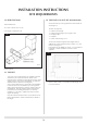
INSTALLATION INSTRUCTIONS INSTALLATION 3 3.1.5 To set the flue length, measure the total wall thickness, then add 65mm. This total flue length will give the minimum clearance of 50mm between the rear of the stove and the wall. To cut the flue to length using a hacksaw, first insert the square cardboard fitment into the flue. This will support the inner flue. Cut through the flue and fitment. See diagram 2. ENSURE THE REMAINING FITMENT IS REMOVED FROM THE FLUE. File the cut edges of the flue smooth.
INSTALLATION INSTRUCTIONS INSTALLATION 3.2.3 If the horizontal terminal is used assemble the required amount of vertical flue including the 90° elbow onto the stove. Drill through the fixing hole in the spigot using a 3.5mm drill and secure with the screw provided. Do not forget the optional decorative collar if you have purchased one. A wall plate is supplied to secure the flue to the inside wall. Bend the tab to 90° and loosely place on the elbow. 3.2 TOP EXIT 3.2.
INSTALLATION INSTRUCTIONS INSTALLATION 3.3 TOP EXIT - VERTICAL FLUE 3.2.6 To determine the length of the terminal flue section measure from the outside of the wall to the stop on the 90° elbow. Horizontal flue sections may fitted between the elbow and the terminal section. See diagram 7. 3.3.1 If a vertical only flue system has been purchased refer to Site Requirements, Diagram 5.
INSTALLATION INSTRUCTIONS INSTALLATION 11 5. FUELBED ARRANGEMENTS Remove the cast iron door using the tool provided. The main ceramic components are inside the firebox. NOTE: THE CAST IRON DOOR IS HEAVY, TAKE EXTREME CARE WHEN HANDLING TO AVOID DAMAGING THE OUTER CASING. The fuel bed consists of 5 logs and 2 ash panels. The logs have letters A,B,C,D and E moulded into them for identification. Take the rear log A and place it up against the rear of the fire sitting on the two flat ledges of the burner.
INSTALLATION INSTRUCTIONS INSTALLATION 5.4 Place the second ash panel to the right of the first, with the pointed end of the panel fitting into the V shape. This panel should locate on the screw holes of the burner skin. Ensure that both logs are horizontal to the burner ports. 5.7 14 Ensure that the fibreglass seal on the back of the door is intact, locate the door on the four studs and slide back to the firebox.
INSTALLATION INSTRUCTIONS COMMISSIONING 1. COMMISSIONING 1.1 Having run the gas supply to the stove, PURGE THE SUPPLY PIPE, this is essential to expel any debris that may block the gas controls. Connect the gas supply to the 8mm compression elbow at the RH rear corner of the stove, see diagram 1. Connect a suitable pressure gauge to the test point located on the inlet fitting, and turn the gas supply on. Light the appliance and check all gas joints for possible leaks.
SERVICING INSTRUCTIONS SERVICING / FAULT FINDING CHARTS 1.4 1. SERVICING REQUIREMENTS 1 20 SYSTEM OK GO TO THE NEXT CHARGE IGNITION FUNCTIONAL CHECK 2 There is a block in the system. Check the inlet test point and the mag seating. NO Has the system got any air in it? YES Purge the gas pipes and retry. YES Is the gas pressure correct? NO Correct and retry. YES NO Is the gas turned on to the appliance? Check isolation tap and gas meter. Retry.
Change the pilot unit. NO YES Tighten the connection and retry. SYSTEM OK Will pilot stay alight? YES Run for 60 seconds, turn off, time interval until mag NO unit shuts with a NO click. Is this greater Change mag unit. than 7 seconds? Replace the thermocouple.
SERVICING INSTRUCTIONS REPLACING PARTS 1. GENERAL 1.1 3. PILOT UNIT All principal components can be replaced without removing the stove from its installation, although it is essential that the gas supply to the appliance is turned off at the isolation device before proceeding further. If, for any reason, the flue has to be removed from the stove, the seals must be replaced. 1.
SERVICING INSTRUCTIONS REPLACING PARTS 3.4 To remove the pilot injector, undo the compression nut on the pilot feed pipe and withdraw the injector which will be hooked onto the olive. When replacing an injector always make sure it is hooked onto the olive before inserting it into the pilot burner. See diagram 4. 6 4 AR1617 7 A AR1604 3.5 To remove the electrode, disconnect the ignition lead and undo the retaining nut.
SERVICING INSTRUCTIONS REPLACING PARTS 4.3 To release the right hand side of the control cover insert the narrow blade screwdriver into the slot shown in diagram 9. Lever it gently and pull from the right hand side at the same time. The cover will now come off, there is a small cylindrical metal spacer inside the cover, this must be kept and replaced on the fixing screw during reassembly. 6.5 6.6 Replace in reverse order.
SERVICING INSTRUCTIONS REPLACING PARTS 8.4 8.5 Holding the injector with a spanner, undo the feed pipe. NOTE: THE ORIENTATION OF THE INJECTOR. Reassemble in reverse order, turn on the gas supply and check for any leaks. 10.
SERVICE RECORDS 1ST SERVICE 2ND SERVICE Date of Service:........................................................................... Date of Service:........................................................................... Next Service Due:....................................................................... Next Service Due:....................................................................... Signed:........................................................................................
Gazco Limited, Osprey Road, Sowton Industrial Estate, Exeter, Devon, England EX2 7JG Tel: (01392) 261999 Fax: (01392) 444148 E-mail: info@gazco.