
Product Manual


1. An emergency crank handle is provided for use in
the event of a power failure. Remove the electrical
power from the winch.
WARNING: NEVER OPERATE THE WINCH ELEC-
TRICALLY WITH THE EMERGENCY HANDLE IN
POSITION.
2. Remove the plastic plug from the side of the winch
housing and insert the handle so that it completely
engages with the drive shaft. The handle can be
cranked in either direction with the clutch in the
engaged position. To make cranking easier, the
clutch can be placed in the free wheel position while
holding onto the emergency handle.
WARNING: IF THE CLUTCH IS PLACED IN FREE
WHEEL FOR HAND CRANKING, BE SURE TO
MAINTAIN A FIRM GRIP ON THE HANDLE AT
ALL TIMES.
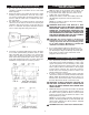
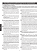
Because the emergency crank handle for models
SA9000AC and SA12000AC attaches to the clutch side
of the winch, it is equipped with a spring operated clip
which will be depressed by the clutch handle in the free
wheel position when cranking in a clockwise direction to
retrieve the cable. This clip is a safety feature and will re-
engage the clutch mechanism in the event that the oper-
ator loses control of the handle with a load on the winch.
(See FIG. 4)
WARNING: EVEN WITH THIS SAFETY FEATURE
THE HANDLE WILL STILL SPIN VIOLENTLY ONE
OR TWO TURNS BEFORE RE-ENGAGING THE
CLUTCH TO STOP THE WINCH. DO NOT LOSE
CONTROL.
3. Always remove the handle from the winch after use
and replace the plastic plug.
For long life and trouble-free operation your winch
should periodically be inspected for any required main-
tenance. This should be done at least once annually and
more frequently in adverse conditions such as salt water
areas or areas of extreme dust and dirt.
1. Carefully inspect the winch cable for any kinks, frays
or abnormal stiffness and replace at the first sign of
this kind of damage. Periodic lubrication with a light
oil will improve the life of the cable. In order to
replace the winch cable, it is necessary to remove
the clutch handle, by removing the two clutch
handle screws, and the four cover mounting bolts.
Be sure that the power is disconnected from the
housing and lift the housing off of the winch by
gently stretching it open near the lower front corner.
Rotate the winch reel so that you have access to the
rope clamp. Remove the old cable and replace it
with a new cable of the same size. Be sure that the
cable passes under both sides of the rope clamp
and that the clamp is tightened securely.
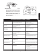
NOTE: CABLE IS WOUND OVER THE TOP OF
THE DRUM ON MODELS SA5000AC AND
SA7000AC AND UNDER THE DRUM ON MODELS
SA9000AC AND SA12000AC. SEE ATTACHMENT
METHOD BELOW (FIG. 5).
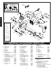
CABLE ATTACHMENT METHODS
2. With the cover removed as described above, inspect
the entire gear train and all drive shafts for any sig-
nificant wear or loose bearing fits. Grease all of the
gears on the inside of the winch base and apply a
drop of oil on all of the bearings in the base. Also,
very sparingly oil all of the bearings in the clutch
mechanism and place a drop of oil on the roller
clutch. Do not over lubricate these areas and do not
use grease in the roller clutch. The clutch mecha-
nism and the brake pads and brake disc must be
kept clean and oil free.
3. Check the operation of the roller clutch. Carefully
rotate the brake disc and observe the motor shaft.
When the disc is turned clockwise the motor shaft
should turn with it. When the disc is turned counter-
clockwise the motor shaft should not turn. Also,
check all nuts, bolts, retaining rings, etc., to be sure
that they are tight and secure.
4. If the clutch has been slipping and requires adjust-
ment the following procedures should be used. The
clutch is adjustable in ten degree increments. With a
screwdriver and pliers, remove the end of the clutch
spring from the hole in the winch base. The spring
tension is quite high so be careful to maintain a firm
grip on the spring. The O-ring should be rotated so
that the cut out portions align with the lugs on the
spring keeper. (See FIG. 6)
The ring can then be expanded with a pencil or simi-
lar object and the spring keeper can be lifted free
from the clutch nut. Rotate the keeper clockwise 10
degrees and install on the next serration in the
clutch nut. Reinstall O-ring and rotate slightly so that
the cut outs are not in line with the lugs on the
spring keeper and reinstall the clutch spring into the
hole in the base. Adjustment of the clutch more than
10 degrees to 20 degrees should normally not be
necessary. With only spring pressure (do not forcibly
Model SA5000/7000AC Model SA9000/12000AC
FIG. 5
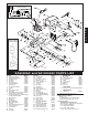
FIG. 4
Emergency Handle
Illustration
AUXILIARY HANDLE
WINCH MAINTENANCE
E
N
G
L
I
S
H
4