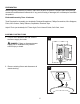
welcoming • sophisticated • inspiring E465631 allen + roth® is a registered trademark of LF, LLC. All Rights Reserved. ITEM #0760102 LED SEMI-FLUSHMOUNT CEILING FIXTURE MODEL #SFL11BNK Français p.11 Español p.21 ATTACH YOUR RECEIPT HERE Purchase Date Questions, problems, missing parts? Before returning to your retailer, call our customer service department at 1-866-439-9800, 8 a.m. - 8 p.m., EST, Monday - Sunday.
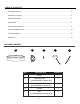
TABLE OF CONTENTS Package Contents ................................................................................................................ 2 Hardware Contents ........................................................................................................................... 3 Safety Information ................................................................................................................ 3 Preparation ........................................................................
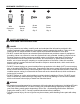
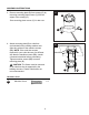
HARDWARE CONTENTS (shown actual size) AA BB Wire Connector Machine Screw Qty. 3 Qty. 2 CC DD 14 mm Screw 8 mm Screw Qty. 3 Qty. 4 SAFETY INFORMATION READ AND SAVE THESE INSTRUCTIONS. DANGER • For your protection and safety, carefully read and understand the information provided in this manual completely before attempting to assemble, install or operate this product. Failure to do so could lead to fire, electrical shock or other injuries that could be hazardous or even fatal.
SAFETY INFORMATION • DO NOT suspend any fixture by the house wires. A fixture must always be mounted directly to an outlet box or to a mounting plate which is first attached to the outlet box. Wire connectors will not support the weight of a fixture. Suspending a fixture by the house wires and wire connectors will result in the fixture falling, with the possibility of personal injury and the danger of electrical shock or fire.
PREPARATION Before beginning assembly of product, make sure all parts are present. Compare parts with package contents list and hardware contents list. If any part is missing or damaged, do not attempt to assemble the product.
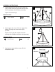
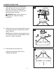
ASSEMBLY INSTRUCTIONS 3 3. Remove mounting plate (B) from canopy (D) by removing mounting plate screws (C) from the edges of the canopy (D). B Save mounting plate screws (C) for later use. C C D 4. Attach mounting plate (B) to outlet box (not included) using existing washers and outlet box screws or the machine screws (BB). NOTE: If the outlet box screws required for your outlet box are of a different size than the machine screws (BB), consult a licensed electrician before proceeding.
ASSEMBLY INSTRUCTIONS 5. Attach bottom end of one arm (E) to fixture (A) using 14 mm screw (CC) provided. Be sure arm (E) is completely secure before proceeding. Repeat for each arm (E). 5 E E CC CC E Hardware Used CC CC x3 14 mm Screw A 6 6. Attach upper end of one of the two arms (E) to canopy (D) using two 8 mm screws (DD) provided. DD Repeat for next arm (E). Tighten all screws securely with a Phillips screwdriver (not provided). D Hardware Used DD 7.
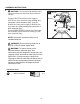
ASSEMBLY INSTRUCTIONS 8. WARNING: Do not remove preattached wire connectors from red and black wires inside the canopy. 8 BLACK AA D NOTE: Screw wire connectors (AA) on in a clockwise direction. WARNING: Never connect ground wire to WHITE or BLACK power supply wires. WARNING: To reduce the risk of fire, electrical shock or personal injury, wire connectors (AA) are designed to accept only one 12-gauge house wire and two lead wires from the light fixture.
ASSEMBLY INSTRUCTIONS 9. Wrap electrical tape (not included) around each individual wire connector (AA) down to the wire. Push wire connectors (AA) gently back into outlet box. Carefully push excess wiring into outlet box. 9 Outlet Box AA WARNING: Make sure no bare wire or wire strands are visible after making connections. AA AA 10. Attach fixture (A) to mounting plate (B) using the mounting plate screws (C) previously removed (Step 3, Page 6).
CARE AND MAINTENANCE • Shut off main power supply. Wipe with soft cloth or use window cleaner. Do not use an abrasive cleaner. • Total wattage for this fixture is 20.55 watts. Do not attempt to replace the LED. TROUBLESHOOTING WARNING: Before beginning work, shut off the power supply to avoid electrical shock. PROBLEM POSSIBLE CAUSE CORRECTIVE ACTION Light does not come on initially or no longer comes on. 1. Power is OFF. 2. Faulty connection. 3. LED component is not working properly. 1.