
Product Manual
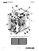
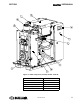
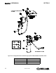
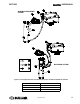
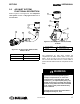
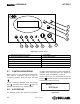
Table Of Contents
- Safety
- Description
- 2.1 Introduction
- 2.2 Compressor Component Description
- 2.3 Compressor Cooling And Lubrication System — Functional Description
- 2.4 Compressor Discharge System—Functional Description
- 2.5 Control System — Functional Description
- 2.6 Air Inlet System, Functional Description
- 2.7 Controller/Keypad
- 2.8 LCD Display
- 2.9 LED LIGHTS
- Specifications
- Installation
- Operation
- Maintenance
- 6.1 General
- 6.2 Maintenance After Initial 50 Hours of Operation
- 6.3 Maintenance Every 2000 Hours
- 6.4 Fluid Maintenance
- 6.5 Filter Maintenance
- 6.6 Air Filter Maintenance
- 6.7 Separator Maintenance
- 6.8 Belt Maintenance
- 6.9 Replacement and Alignment of Belt Pulleys
- 6.10 Hose Maintenance
- 6.11 TANK MOUNT PACKAGE MAINTENANCE
- 6.12 Troubleshooting – Introduction

SHOPTEK
™
USER MANUAL SECTION 2
16
02250180-090 R00
service line pressure will rise. The Controller de-
energizes the solenoid valve when the pressure
exceeds 127 psig (8.8 bar) allowing the separator
tube air pressure to be supplied directly which closes
the inlet valve. At the same time the solenoid valve
exhausts the system pressure to the atmosphere and
lowers the separator tube pressure to approximately
29 psig (2.0 bar). A check valve in the air service line
prevents air from back-flowing to the separator tube.
When the pressure drops to the low setting: (cut-in
pressure) usually 112 psig (7.7 bar) for high pressure
(9 bar) compressors, 137 psig (9.4 bar) for (10 bar)
compressors, 161 psig (11.1 bar) for (12 bar)
compressors: the Controller energizes the solenoid
valve and prevents line pressure from reaching the
inlet control valve.
Figure 2-6: Control System, ST1100, ST1500, 15-20 HP
1. Air Outlet 5. Separator Tube
2. Unload Solenoid Valve 6. Pressure Transducer
3. Air Inlet 7. Controller
4. Minimum Pressure/Check Valve