USER MANUAL REFRIGERATED AIR DRYER SR 10-480 AC WARRANTY NOTICE Failure to follow the instructions and procedures in this manual or, misuse of this equipment will VOID its warranty! SAFETY WARNING Users are required to read the entire User Manual before handling or using the product. Keep the User Manual in a safe place for future reference.
User Manual US-EN SR 10-480 AC Dear customer, Thank you for deciding in favour of the SR 10-480 AC compressed-air refrigeration dryer. Please read these installation and operating instructions carefully before mounting and starting up the SR 10-480 AC and follow our directions. Perfect functioning of the SR 10-480 AC and thus reliable compressed-air drying can only be guaranteed when the provisions and notes stipulated here are strictly adhered to. 02250246-045 R02 2 Subject to EAR.
User Manual US-EN SR 10-480 AC Contents 1 Name plate 6 2 Safety instructions 6 2.2 Safety pictograms in accordance with DIN 4844 7 2.3 Signal words in accordance with ANSI 8 2.4 Overview of the safety instructions 8 3 Proper use 13 4 Exclusion from a field of application 13 5 Instructions for the use of pressure equipment according to PED directive 2014/68/EU 13 6 Transport 15 7 Storage 15 8 Installation 15 8.1 Place of installation 15 8.2 Installation plan 16 8.
User Manual US-EN SR 10-480 AC 11.8 Aluminium heat exchanger 28 11.9 Hot-gas bypass valve 28 11.10 Refrigerant pressure switches LPS – HPS – PV 30 11.11 Safety temperature switch TS 30 11.12 DMC 15 electronics (control unit compressed-air dryer) 31 11.12.1 Switching the dryer on 31 11.12.2 Switching the dryer off 31 11.12.3 Indication of a service warning/service alarm 31 11.12.4 Control of the condenser fan (SR 10-100) 33 11.12.5 Control of the drain solenoid valve 33 11.12.
User Manual US-EN SR 10-480 AC 13.2.2 Exploded diagram SR 10-15 AC 55 13.2.3 Exploded diagram SR 20-35 AC 56 13.2.4 Exploded diagram SR 50 AC 57 13.2.5 Exploded diagram SR 75-100 AC 58 13.2.6 Exploded diagram SR 125-220 AC 59 13.2.7 Exploded diagram SR 300-375 AC 60 13.2.8 Exploded diagram SR 480 AC 61 13.3 Electric diagrams 62 13.3.1 Electric diagrams – list of components 62 13.3.2 Electric diagram SR 10-100 AC 63 13.3.3 Electric diagram SR 125-175 AC 64 13.3.
User Manual US-EN 1 SR 10-480 AC Name plate The name plate is on the back of the dryer and comprises all primary data of the device. Always refer to these when contacting the manufacturer or the sales department. Note: Alternative nomenclature SRB. All guarantee claims will expire in the event that the name plate is modified or removed. 2 Safety instructions Pos : 2 /Sull air Technisc he Dokumentation/Global e T e xte/Allgemei ner Hinweis BM @ 0\mod_1183615737313_6.
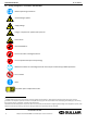
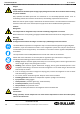
User Manual US-EN 2.2 SR 10-480 AC Safety pictograms in accordance with DIN 4844 Observe operating instructions General danger symbol Supply voltage Danger: component or system under pressure Hot surfaces Non-breathable air Do not use water to extinguish the fire Do not operate with open cover (housing) Maintenance works or controlling measures must only be carried out by qualified personnel1 Do not smoke Note Pos: 4 /Sullair Technische Dokumentation/Sicherheit/Gefahr Druckluft @ 0\mod_11841481
User Manual US-EN ARIA AIR LUFT AIR SR 10-480 AC Connection point compressed-air outlet Connection point condensate drain Works can be carried out by the operator of the plant, provided that they are skilled accordingly1. NOTE: Text that contains important specifications to be considered – does not refer to safety precautions.
User Manual US-EN SR 10-480 AC For safe operation, the device must only be installed and operated in accordance with the indications in the operating instructions. In addition, the national and operational statutory provisions and safety regulations, as well as the accident prevention regulations required for the respective case of application, need to be observed during employment. This applies accordingly when accessories are used.
User Manual US-EN SR 10-480 AC os: 5 6/Sullair Druckluft BM 0\mod_1184148284291_6.doc 5812 Pos: /SullairTechnische TechnischeDokumentation/Sicherheit/Maßnahmen Dokumentation/Sicherheit/Gefahr Netzspannung @@ 0\mod_1184148186948_6.doc @@ 5794 Danger! Supply voltage! Contact with non-insulated parts carrying supply voltage involves the risk of an electric shock resulting in injuries and death. Only qualified and skilled personnel are authorised to run electrically-operated devices.
User Manual US-EN SR 10-480 AC All components concerned are installed inside of the closed housing. The housing must only be opened by certified skilled personnel2. Caution! Improper use! The device is intended for the separation of water in compressed air. The dried air cannot be used for breathing-air purposes and is not suitable for the direct contact with food. This dryer is not suitable for the treatment of contaminated air or of air containing solids.
User Manual US-EN SR 10-480 AC Unauthorised interventions, modification and abuse of the pressure devices are prohibited. The removal of sealings and leadings at safety devices is prohibited. Operators of the devices must observe the local and national pressure equipment regulations in the country of installation. Pos: 8 @ /Sullair Dokumentation/Sicherheit/Sicherheitshinweise, weitere BM (nicht Ex) @Sicherheitshinweise 0\mod_1183616103770_6.
User Manual US-EN 3 SR 10-480 AC Proper use This dryer was designed, manufactured and tested to separate the moisture which normally exists in compressed air. Any other use is considered improper. The manufacturer shall not be liable for problems occurring as a consequence of improper use. The user alone is responsible for any damage resulting from that.
User Manual US-EN SR 10-480 AC • No objects whatsoever must be installed at or placed on the SR 10-480 AC compressed-air refrigeration dryer and the connecting lines. • Installation of the plant in frost-free places only. • Operation of the plant is only permissible with fully closed and intact housing and cover panels. Operation of the plant with damaged housing/cover panels is prohibited. 02250246-045 R02 14 Subject to EAR. ECCN EAR99 and related export control restrictions.
User Manual US-EN 6 SR 10-480 AC Transport Check the packaging for visible loss or damage. If no visible damage can be ascertained, place the unit in close proximity to the place of installation and unpack the device. During this procedure, the dryer must always remain in an upright position. The components may be damaged when the unit is tilted or turned upside down. Store the device in a dry environment and do not expose it to extreme weather conditions. Handle with care.
User Manual US-EN 8.2 SR 10-480 AC Installation plan 8 -AIN 7 OUT 3 4 5 9 1 2 9 8 -BIN 7 OUT 3 Air compressor 2 Aftercooler 3 Condensate separator 4 Prefilter 5 Bypass group 6 Dryer 7 Compressed-air tank 8 Final filter 9 Sullimax condensate drain 6 9 9 1 4 9 5 1 2 9 6 9 9 Installation type A is recommended when the total consumption corresponds to the throughput rate of the compressor.
User Manual US-EN 8.4 SR 10-480 AC Correction factors Correction factor for operating pressure modifications: Inlet air pressure psig 60 80 100 120 140 160 180 203 barg 4 5.5 7 8 10 11 12 14 0.79 0.91 1.00 1.07 1.13 1.18 1.23 1.27 Factor (F1) Correction factor for ambient temperature modifications: Ambient temperature ºF 80 90 95 100 105 110 115 ºC 27 32 35 38 40 43 45 1.07 1.04 1.00 0.93 0.83 0.70 Factor (F2) 1.
User Manual US-EN SR 10-480 AC Actual air throughput = 75 x 1.07 x 0.93 x 0.65 x 1.25 = 61 scfm (104 m³/h) 61 scfm (104 m³/h) is the maximum flow rate of the dryer under the aforementioned operating conditions. Selection of the best suitable model in accordance with the operating conditions: Requ. air throughput Air throughput acc.
User Manual US-EN SR 10-480 AC Note! Contaminated intake air! In the event that the intake air is strongly contaminated (ISO 8573.1 class 3.-3) or poorer quality, we recommend the additional installation of a prefilter (e.g. Sullair STX or SXF), to avoid clogging of the heat exchanger. 8.6 Electrical connections Danger! Supply voltage! The connection to the electric mains should only be carried out by qualified skilled personnel and must correspond to the legal provisions in force in your region.
User Manual US-EN 9 SR 10-480 AC Start-up 9.1 Preliminary stages Note! Exceeding of the operating parameters! Ensure that the operating parameters comply with the nominal values indicated on the name plate of the dryer (voltage, frequency, air pressure, air temperature, ambient temperature etc.). Prior to delivery, this dryer was thoroughly tested, packed and checked.
User Manual US-EN SR 10-480 AC • Ensure that the fan runs properly – wait for the first interventions. • Wait until the dew point remains stable. • Slowly open the air inlet valve. • Slowly open the air outlet valve. • Slowly close the central bypass valve of the system (if installed). • Check the pipes for air leakage. • Ensure the proper functioning of the condensate drain cycle (wait for the first condensate discharges).
User Manual US-EN SR 10-480 AC The user is responsible for the compliance with these provisions. Irreparable damage can be caused when starting up the device too often. 02250246-045 R02 22 Subject to EAR. ECCN EAR99 and related export control restrictions.
User Manual US-EN SR 10-480 AC 10 Technical data 10.1 Technical data SR 10-480 -P (1/115/60) UL 02250246-045 R02 23 Subject to EAR. ECCN EAR99 and related export control restrictions.
User Manual US-EN SR 10-480 AC 10.2 Technical data SR 125-480 NA -E (1/230/60) UL 02250246-045 R02 24 Subject to EAR. ECCN EAR99 and related export control restrictions.
User Manual US-EN SR 10-480 AC 11 Technical description 11.1 Control panel The control panel explained below is the only dryer user interface. SR 10 – 175 AC K 1 ON DMC15 0 sec - min Set PQS0008 1 3 2 SR 220 – 480 AC K I ON ON DMC15 sec - min PQS0024 Set 1 2 3 1 ON-OFF Switch 2 Electronic instrument 3 Air and refrigerant flow diagram 11.2 Functional description Operating principle – All dryer models described in this manual function according to the same principle.
User Manual US-EN SR 10-480 AC pressure. The liquid is pressed through a capillary tube where the resulting pressure drop ensures that the refrigerant evaporates at a defined temperature. The liquid refrigerant which is under low pressure is led into the heat exchanger, where it expands. The cold resulting from the expansion serves to cool down the compressed air in the heat exchanger. During this process, the refrigerant evaporates.
User Manual US-EN SR 10-480 AC 11.3 Flow chart 1 Aluminium heat exchanger module Sullimax 9 Condenser fan a – Air/air heat exchanger 10 Filter dryer b – Air/refrigerant heat exchanger 11 Capillary tube c – Condensate separator 12.1 T1 temperature sensor (dew point) 2 Refrigerant pressure switch LPS (SR 480) 12.2 Temperature probe T2 – Fan control (SR 10-100) 3 Safety temperature switch TS (SR 220-480) 13 Condensate drain shut-off valve 4 Refrig.
User Manual US-EN SR 10-480 AC 11.4 Refrigerating compressor The employed refrigerating compressors are constructed by leading manufacturers. The hermetically sealed construction is absolutely gastight. The integrated safeguard protects the compressor against overheating and excess current. The protection is automatically reset as soon as the nominal conditions are reached again. 11.
User Manual US-EN SR 10-480 AC ADJUSTMENT The hot gas by-pass valve is adjusted during the manufacturing testing phase. As a rule no adjustment is required; anyway if it is necessary the operation must be carried out by an experienced refrigerating engineer. A 4 mm 5/32 in. WARNING the use of ¼” Schrader service valves must be justified by a real malfunction of the refrigerating system. Each time a pressure gauge is connected, a part of refrigerant is exhausted.
User Manual US-EN SR 10-480 AC 11.10 Refrigerant pressure switches LPS – HPS – PV To ensure the operational reliability and the protection of the dryer, a series of pressure switches are installed in the gas cycle. LPS : Low-pressure guard on the suction side of the compressor, which is triggered when the pressure drops below the predetermined value. The values are reset automatically as soon as the nominal conditions are reestablished. Calibrated pressure : R 407 C HPS : Stop 24.7 psig (1.
User Manual US-EN SR 10-480 AC 11.12 DMC 15 electronics (control unit compressed-air dryer) ON ON DMC15 Led - Drain ON sec - min PQS0036 Led – Power ON Led – Condenser fan ON (SR 10-100) Set Set DISPLAY Button – Setup menu access Button – Increase / Drain test The DMC15 displays DewPoint temperature, controls the condenser fan activation and the timed drainer. 11.12.1 Switching the dryer on Power the dryer and switch it on using the ON-OFF switch (pos.1 paragraph 11.1).
User Manual US-EN SR 10-480 AC NOTE : fan is forced always ON. Display 10th (right) led is flashing DewPoint too high DewPoint too low Display 1st (left) led is flashing (lower than -1°C / 30°F). 02250246-045 R02 32 Subject to EAR. ECCN EAR99 and related export control restrictions.
User Manual US-EN SR 10-480 AC 11.12.4 Control of the condenser fan (SR 10-100) A temperature probe T2 is located on the discharge side of the condenser. The condenser fan is activated (ON) when the T2 temperature is higher than FANon setting (standard 35°C / 96°F) and led is ON. Condenser fan stops at T2 temperatures 5°C / 10°F lower than FANon setting (standard 30°C / 86°F). 11.12.
User Manual US-EN SR 10-480 AC These Sullimax condensate drains were designed in particular for the operation in a SR refrigeration dryer. The installation in other compressed-air processing systems or the replacement with another drain brand can lead to malfunction. The maximum operating pressure (see name plate) must not be exceeded! Ensure that the upstream valve is open when the dryer starts operation.
User Manual US-EN SR 10-480 AC Only qualified and skilled personnel are authorised to run electrically-operated devices. Prior to undertaking maintenance measures at the device, the following requirements must be met: Make sure that the power supply is switched off and that the device is off and marked for maintenance measures. Please also ensure that the power supply cannot be re-established during the works.
User Manual US-EN SR 10-480 AC DAILY: • Check whether the dew point indicated on the electronics is correct. • Ensure that the condensate drain system functions properly. • Make sure that the condenser is clean. EVERY 200 HOURS OR MONTHLY • Clean the condenser using an air jet (max. 2 bar / 30 psig) inside out. Make sure not to damage the aluminium lamellae of the cooling package. • Finally, verify the operation of the device.
User Manual US-EN SR 10-480 AC 12.2 Troubleshooting Certified skilled personnel Installation works must exclusively be carried out by authorised and qualified skilled personnel. Prior to undertaking any measures on the SR 10-480 AC compressed-air refrigeration dryer, the certified skilled personnel shall read up on the device by carefully studying the operating instructions. The operator is responsible for the adherence to these provisions.
User Manual US-EN SR 10-480 AC All components concerned are installed inside of the closed housing. The housing must only be opened by certified skilled personnel. Some components can reach high temperatures during operation. Avoid any contact until the system or the component has cooled down. POSSIBLE REASON – SUGGESTED MEASURE FAULT The dryer does not start. Check whether or not the dryer is connected with the electric mains. Check the electric cabling.
User Manual US-EN SR 10-480 AC The dryer does not discharge the condensate – see the corresponding point. The hot-gas bypass valve needs to be re-adjusted – contact a SULLAIR service technician to have the nominal setting re-established. There is a leak in the refrigeration cycle – contact a SULLAIR service technician. Dew point too low.
User Manual US-EN SR 10-480 AC The condensate drain service valve is closed - open it. The dryer does not drain the condensate. Condensate strainer is clogged – remove and clean it. The drain solenoid valve is jammed – remove and clean it. Verify the electric wiring. The coil of the drain solenoid valve is failed – replace it. Electronic instrument is faulty – repace it. The DewPoint is too low - the condensate is frost and blocks the air - see specific point.
User Manual US-EN If installed: the TS safety temperature switch was triggered. SR 10-480 AC Check which of the following reasons is responsible for the triggering: Excess thermal load – re-establish the standard operating conditions. The inlet air is too hot – re-establish the nominal conditions. The ambient temperature is too high or the room ventilation insufficient – ensure sufficient ventilation. The condenser unit is dirty – please clean it. The fan does not work – see the corresponding point.
User Manual US-EN SR 10-480 AC 12.3.
User Manual US-EN SR 10-480 AC 12.3.
User Manual US-EN SR 10-480 AC 12.4 Maintenance works at the refrigeration cycle Caution! Refrigerant! Maintenance and repair works at refrigeration systems must only be carried out by SULLAIR service technicians in accordance with the local provisions. The total amount of refrigerant in the system must be collected for recycling purposes, resource recovery or disposal. The refrigerant must not be discharged into the environment.
User Manual US-EN SR 10-480 AC Electric cable Copper, PVC Electric parts PVC, copper, brass We recommend observing the safety provisions in force for the disposal of each material type. The refrigerant contains lubricating-oil droplets which are released by the compressor. The refrigerant must not be discharged into the environment. It must to be sucked off from the dryer using a suitable device, and then needs to be supplied to a collection point. 02250246-045 R02 45 Subject to EAR.
User Manual US-EN SR 10-480 AC 13 Appendices 13.1 Dryer dimensions 13.1.1 Dryer dimensions SR 10-15 AC 02250246-045 R02 46 Subject to EAR. ECCN EAR99 and related export control restrictions.
User Manual US-EN SR 10-480 AC 13.1.2 Dryer dimensions SR 20-50 AC 02250246-045 R02 47 Subject to EAR. ECCN EAR99 and related export control restrictions.
User Manual US-EN SR 10-480 AC 13.1.3 Dryer dimensions SR 75 AC 02250246-045 R02 48 Subject to EAR. ECCN EAR99 and related export control restrictions.
User Manual US-EN SR 10-480 AC 13.1.4 Dryer dimensions SR 100 AC 02250246-045 R02 49 Subject to EAR. ECCN EAR99 and related export control restrictions.
User Manual US-EN SR 10-480 AC 13.1.5 Dryer dimensions SR 125-150 AC 02250246-045 R02 50 Subject to EAR. ECCN EAR99 and related export control restrictions.
User Manual US-EN SR 10-480 AC 13.1.6 Dryer dimensions SR 175-220 AC 02250246-045 R02 51 Subject to EAR. ECCN EAR99 and related export control restrictions.
User Manual US-EN SR 10-480 AC 13.1.7 Dryer dimensions SR 300-375 AC 02250246-045 R02 52 Subject to EAR. ECCN EAR99 and related export control restrictions.
User Manual US-EN SR 10-480 AC 13.1.8 Dryer dimensions SR 480 AC 02250246-045 R02 53 Subject to EAR. ECCN EAR99 and related export control restrictions.
User Manual US-EN SR 10-480 AC 13.2 Exploded diagrams 13.2.1 Components of the exploded diagrams 1 Alu drying module 16 Coil for condensate drain solenoid valve 1.
User Manual US-EN SR 10-480 AC 13.2.2 Exploded diagram SR 10-15 AC Timed 02250246-045 R02 55 Subject to EAR. ECCN EAR99 and related export control restrictions.
User Manual US-EN SR 10-480 AC 13.2.3 Exploded diagram SR 20-35 AC Timed 02250246-045 R02 56 Subject to EAR. ECCN EAR99 and related export control restrictions.
User Manual US-EN SR 10-480 AC 13.2.4 Exploded diagram SR 50 AC Timed 02250246-045 R02 57 Subject to EAR. ECCN EAR99 and related export control restrictions.
User Manual US-EN SR 10-480 AC 13.2.5 Exploded diagram SR 75-100 AC Timed 02250246-045 R02 58 Subject to EAR. ECCN EAR99 and related export control restrictions.
User Manual US-EN SR 10-480 AC 13.2.6 Exploded diagram SR 125-220 AC Timed 02250246-045 R02 59 Subject to EAR. ECCN EAR99 and related export control restrictions.
User Manual US-EN SR 10-480 AC 13.2.7 Exploded diagram SR 300-375 AC Timed 02250246-045 R02 60 Subject to EAR. ECCN EAR99 and related export control restrictions.
User Manual US-EN SR 10-480 AC 13.2.8 Exploded diagram SR 480 AC Timed 02250246-045 R02 61 Subject to EAR. ECCN EAR99 and related export control restrictions.
User Manual US-EN SR 10-480 AC 13.3 Electric diagrams 13.3.
User Manual US-EN SR 10-480 AC 13.3.2 Electric diagram SR 10-100 AC 02250246-045 R02 63 Subject to EAR. ECCN EAR99 and related export control restrictions.
User Manual US-EN SR 10-480 AC 13.3.3 Electric diagram SR 125-175 AC 02250246-045 R02 64 Subject to EAR. ECCN EAR99 and related export control restrictions.
User Manual US-EN SR 10-480 AC 13.3.4 Electric diagram SR 220 AC 02250246-045 R02 65 Subject to EAR. ECCN EAR99 and related export control restrictions.
User Manual US-EN SR 10-480 AC 13.3.5 Electric diagram SR 300 AC 02250246-045 R02 66 Subject to EAR. ECCN EAR99 and related export control restrictions.
User Manual US-EN SR 10-480 AC 13.3.6 Electric diagram SR 375 AC 02250246-045 R02 67 Subject to EAR. ECCN EAR99 and related export control restrictions.
User Manual US-EN SR 10-480 AC 13.3.7 Electric diagram SR 480 AC 02250246-045 R02 68 Subject to EAR. ECCN EAR99 and related export control restrictions.
Sullair, LLC 1 Sullair Way Michigan City, IN 46360 USA www.sullair.com 1-800-SULLAIR (USA only) 1-219-879-5451 (non-USA) Information and specifications are subject to change without prior notice. Subject to EAR, ECCN AR99 and related export control restrictions.