USER MANUAL REFRIGERATED AIR DRYER SRHT 20-350 AC WARRANTY NOTICE MANUAL PART NUMBER: 02250246-084 R01 Failure to follow the instructions and procedures in this manual or, misuse of this equipment will VOID its warranty! ©SULLAIR LLC
User Manual US-EN SRHT 20-350 AC Dear customer, Thank you for deciding in favour of the SRHT 20-350 AC compressed-air refrigeration dryer. Please read these installation and operating instructions carefully before mounting and starting up the SRHT 20-350 AC and follow our directions. Perfect functioning of the SRHT 20-350 AC and thus reliable compressed-air drying can only be guaranteed when the provisions and notes stipulated here are strictly adhered to. 02250246-084 R01 2 Subject to EAR.
SRHT 20-350 AC User Manual US-EN Contents 1 Name plate 6 2 Safety instructions 6 2.1 Safety pictograms in accordance with DIN 4844 7 2.2 Signal words in accordance with ANSI 9 2.3 Overview of the safety instructions 9 3 Proper use 12 4 Exclusion from a field of application 13 5 Instructions for the use of pressure equipment according to PED directive 2014/68/EU 13 6 Transport 14 7 Storage 14 8 Installation 14 8.1 Place of installation 14 8.2 Installation plan 16 8.
User Manual US-EN SRHT 20-350 AC 11.8 Filter dryer 30 11.9 Capillary tube 30 11.10 Aluminium heat exchanger 30 11.11 Hot-gas bypass valve 30 11.12 Refrigerant pressure switches LPS – HPS – PV 32 11.13 Safety temperature switch TS 32 11.14 Aftercooler safety thermo-switch TSA 32 11.15 DMC 14 electronics (control unit compressed-air dryer) 33 11.15.1 How to switch on the dryer 33 11.15.2 How to switch off the dryer 33 11.15.3 How to display the operating parameters 33 11.15.
SRHT 20-350 AC User Manual US-EN 13.2 Exploded diagrams 55 13.2.1 Components of the exploded diagrams 55 13.2.2 Exploded diagram SRHT 20-50 AC 56 13.2.3 Exploded diagram SRHT 75 AC 57 13.2.4 Exploded diagram SRHT 100 AC 58 13.2.5 Exploded diagram SRHT 150-250 AC 59 13.2.6 Exploded diagram SRHT 300-350 AC 60 13.3 Electric diagrams 61 13.3.1 Electric diagrams – list of components 61 13.3.2 Electric diagram SRHT 20-50 AC 63 13.3.3 Electric diagram SRHT 75-100 AC 64 13.3.
User Manual US-EN 1 SRHT 20-350 AC Name plate The name plate is on the back of the dryer and comprises all primary data of the device. Always refer to these when contacting the manufacturer or the sales department. All guarantee claims will expire in the event that the name plate is modified or removed. 2 Safety instructions Pos : 2 /SULLAIR T ec hnis che D okumentati on/Gl obale Texte/Allgemeiner Hi nweis BM @ 0\mod_1183615737313_6.
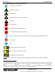
SRHT 20-350 AC 2.1 User Manual US-EN Safety pictograms in accordance with DIN 4844 Observe operating instructions General danger symbol Supply voltage Danger: component or system under pressure Hot surfaces Non-breathable air Do not use water to extinguish the fire Do not operate with open cover (housing) Maintenance works or controlling measures must only be carried out by qualified personnel1 Do not smoke Note Pos: 4 /SULLAIR Technische Dokumentation/Sicherheit/Gefahr Druckluft @ 0\mod_118414
User Manual US-EN SRHT 20-350 AC NOTE: Text that contains important specifications to be considered – does not refer to safety precautions.
SRHT 20-350 AC 2.
User Manual US-EN SRHT 20-350 AC Only qualified and skilled personnel are authorised to run electrically-operated devices. Prior to undertaking maintenance measures at the device, the following requirements must be met: Make sure that the power supply is switched off and that the device is off and marked for maintenance measures. Please also ensure that the power supply cannot be re-established during the works.
SRHT 20-350 AC User Manual US-EN Caution! Hot surfaces! During operation, several components can reach surface temperatures of more than 140°F (60°C). There is the risk of burns. All components concerned are installed inside of the closed housing. The housing must only be opened by certified skilled personnel2. Caution! Improper use! The device is intended for the separation of water in compressed air.
User Manual US-EN SRHT 20-350 AC Note! Contaminated intake air! In the event that the intake air is strongly contaminated (ISO 8573.1 class 3.-3 or poorer quality), we recommend the additional installation of a prefilter (e.g. SULLAIR SXT OR SXF), to avoid clogging of the heat exchanger. Caution! Heating-up through fire! In the event of a heating-up through fire, the containers and pipes of the refrigerant system can burst. In this case, please proceed as follows: Switch off the refrigeration plant.
SRHT 20-350 AC User Manual US-EN Furthermore, the correct use includes the compliance with the installation instructions, in particular in respect of: • The voltage and frequency of the main voltage supply. • The pressure, temperature and flow rate of the inlet air. • The ambient temperature. When delivered, the dryer is tested and fully assembled. The customer only needs to connect the device to the system in accordance with the instructions in the following chapters.
User Manual US-EN 6 SRHT 20-350 AC Transport Check the packaging for visible loss or damage. If no visible damage can be ascertained, place the unit in close proximity to the place of installation and unpack the device. During this procedure, the dryer must always remain in an upright position. The components may be damaged when the unit is tilted or turned upside down. Store the device in a dry environment and do not expose it to extreme weather conditions. Handle with care.
SRHT 20-350 AC User Manual US-EN Minimum installation requirements: 14in - 354mm 40in - 1m • Select a clean dry area, free from dust, and protected from atmospheric disturbances. • The supporting area must be smooth, horizontal and able to hold the weight of the dryer. 1.1/4in 30mm 3/8in - 10mm 1in - 26mm • Minimum ambient temperature +34 °F (+1 °C). • Maximum ambient temperature +120°F (50°C).
User Manual US-EN 8.2 SRHT 20-350 AC Installation plan IN 5.1 -A- 4 5.2 6 OUT 5.3 1 1 Air compressor 4 By-pass group 5 Dryer 5.1 Aftercooler 5.2 Pre-Filter 5.3 Alu-Dry Module 8 IN 5.1 -B- 4 5.2 6 6 Compressed-air tank 8 Sullimax condensate drain OUT 5.3 1 5 8 8 8 Installation type A is recommended when the total consumption corresponds to the throughput rate of the compressor.
SRHT 20-350 AC 8.3 User Manual US-EN Correction factors Correction factor for operating pressure modifications: Inlet air pressure psig 60 80 100 120 140 160 180 200 220 230 barg 4 5.5 7 8 10 11 12.5 14 15 16 0.79 0.91 1.00 1.07 1.13 1.18 1.23 1.27 1.31 1.33 Factor (F1) Correction factor for ambient temperature modifications: Ambient temperature ºF 80 90 100 105 110 115 120 ºC 27 32 38 40 43 46 50 1.11 1.00 0.94 0.89 0.83 0.78 Factor (F2) 1.
User Manual US-EN SRHT 20-350 AC Every function parameter corresponds to a numerical factor which, multiplied by the planned nominal capacity, determines the following: Air flow capacity = 150 x 1.07 x 0.94 x 0.90 x 1.00 = 137 scfm. (233 m³/h) 137 scfm (233 m³/h) This is the maximum flow rate that the dryer can accept under these operating conditions. How to select a suitable dryer for a given duty: Design air flow Minimum std.
SRHT 20-350 AC User Manual US-EN The dryer was designed in such a manner that vibrations that may occur during operation are limited. Therefore, it is advisable to employ connecting lines (flexible hoses, vibration-inhibiting fittings etc.) which protect the dryer against possible vibrations in the pipework. Note! Contaminated intake air! In the event that the intake air is strongly contaminated (ISO 8573.1 class 3.-3) or poorer quality, we recommend the additional installation of a prefilter (e.g.
User Manual US-EN SRHT 20-350 AC Never direct the condensate drain pipe at persons. The dryer is delivered with an already integrated timed condensate drain or an electronically level-controlled SULLIMAX condensate drain. Connect the condensate drain with a collection system or container by properly screwing it on. Do not connect the drain with pressurised plants. Do not discharge the condensate into the environment.
SRHT 20-350 AC User Manual US-EN The method below should be applied during the first start-up, after longer downtimes or subsequent to maintenance works. The start-up must be carried out by certified skilled personnel. Processing sequence (see Section 11.1 "Control panel") • Ensure that all the steps of the “Installation” chapter have been observed. • Ensure that the connection to the compressed air system is correct and that the piping is suitably fixed and supported.
User Manual US-EN 9.3 SRHT 20-350 AC Start-up and shut down Start-up (refer to paragraph 11.1 Control Panel) • Check the condenser for cleanliness. • Verify that the system is powered. • Activate the main switch - pos. 1 on the control panel. • Ensure that electronic controller DMC14 is ON. • Wait a few minutes; verify that the DewPoint temperature displayed on electronic instrument DMC14 is correct and that the condensate is regularly drained. • Switch on the air compressor.
SRHT 20-350 AC User Manual US-EN 10 Technical data 10.1 Technical data SRHT 20-150 AC (1/115/60) 02250246-084 R01 Subject to EAR. ECCN EAR99 and related export control restrictions.
User Manual US-EN SRHT 20-350 AC 02250246-084 R01 24 Subject to EAR. ECCN EAR99 and related export control restrictions.
SRHT 20-350 AC User Manual US-EN 10.2 Technical data SRHT 150-350 AC Z (1/230/60) 02250246-084 R01 Subject to EAR. ECCN EAR99 and related export control restrictions.
User Manual US-EN SRHT 20-350 AC 11 Technical description 11.1 Control panel The control panel explained below is the only dryer user interface. SRHT 20 – 100 AC K 1 DMC14 PQS0003 0 1 3 2 SRHT 150 – 350 AC K I ON °C °F PQS0004 set 1 DMC 14 esc 2 3 1 ON-OFF Switch 2 Electronic instrument 3 Air and refrigerant flow diagram 11.2 Functional description Operating principle – The dryer models described in this manual all operate on the same principal.
SRHT 20-350 AC User Manual US-EN Refrigeration cycle – Refrigerant gas is cycled through the compressor and exits at high pressure to a condenser where heat is removed causing the refrigerant to condense to a high-pressure liquid state. The liquid is forced through a capillary tube where the resulting pressure drop allows the refrigerant to boil off at a predetermined temperature.
User Manual US-EN SRHT 20-350 AC 11.3 Flow chart Aluminium heat exchanger module 10 Filter dryer a – Air/air heat exchanger 11 Capillary tube b – Air/refrigerant heat exchanger 12 T1 temperature sensor (DewPoint) c – Condensate separator 13 Condensate drain shut-off valve 14 Condensate drain strainer 15 Condensate drain solenoid valve 3.
SRHT 20-350 AC User Manual US-EN (HT 300-350 NA UL) 5 Refrigerant fan pressure switch PV 21 SULLIMAX condensate drain 6 Refrigerating compressor 26 Aftercooler 7 Hot-gas bypass valve 27 Aftercooler fan (SRHT 75-350 AC) 8 Condenser 28 Pre-Filter (1 micron) 9 Condenser fan Compressed-air flow direction Refrigerant gas flow direction 02250246-084 R01 Subject to EAR. ECCN EAR99 and related export control restrictions.
User Manual US-EN SRHT 20-350 AC 11.4 Refrigerating compressor The employed refrigerating compressors are constructed by leading manufacturers. The hermetically sealed construction is absolutely gastight. The integrated safeguard protects the compressor against overheating and excess current. The protection is automatically reset as soon as the nominal conditions are reached again. 11.
SRHT 20-350 AC User Manual US-EN ADJUSTMENT The hot gas by-pass valve is adjusted during the manufacturing testing phase. As a rule no adjustment is required; anyway if it is necessary the operation must be carried out by an experienced refrigerating engineer. A 4 mm 5/32 in. WARNING the use of ¼” Schrader service valves must be justified by a real malfunction of the refrigerating system. Each time a pressure gauge is connected, a part of refrigerant is exhausted.
User Manual US-EN SRHT 20-350 AC 11.12 Refrigerant pressure switches LPS – HPS – PV To ensure the operational reliability and the protection of the dryer, a series of pressure switches are installed in the gas cycle. LPS : Low-pressure guard on the suction side of the compressor, which is triggered when the pressure drops below the predetermined value. The values are reset automatically as soon as the nominal conditions are reestablished.
SRHT 20-350 AC User Manual US-EN 11.15 DMC 14 electronics (control unit compressed-air dryer) Led - Temperature in °C Led - Temperature in °F PQS0050 Led – Drain ON Led – Alarm/Service Set Set Button – Setup menu access Button – Decrease DISPLAY Button – Increase / Drain test The DMC14 controls the alarms and the settings of the dryer operations and the timed drainer. 11.15.1 How to switch on the dryer Power the dryer and switch it on using the ON-OFF switch (pos. 1 paragraph 7.1).
User Manual US-EN SRHT 20-350 AC flashing + low temperature on display Low DewPoint : DewPoint too low, lower than -2.0°C / 28°F (delay 30 seconds). Alarm disappears when temperature becomes higher than -0.5°C / 31°F. 02250246-084 R01 34 Subject to EAR. ECCN EAR99 and related export control restrictions.
SRHT 20-350 AC User Manual US-EN 11.15.5 How is controlled the drain solenoid valve Drain solenoid valve is activated (ON) for seconds (standard 2 seconds) every minute). Led shows that condensate drain solenoid valve is ON. The condensate drain test is always active using the button minutes (standard 1 . 11.15.6 Operation of the failure / alarm dry contact The DMC14 is equipped with a dry contact (potential free) to display failure and/or alarm conditions.
User Manual US-EN SRHT 20-350 AC These SULLIMAX condensate drains have been specially designed for the use in a refrigerant dryer SRHT AC. Any Installation in other compressed air treatment units or the exchange against a different drain brand may lead to malfunction. Do not exceed the max. operating pressure (see type plate)! Make sure when the dryer starts the upstream valve is open.
SRHT 20-350 AC User Manual US-EN Danger! Supply voltage! Contact with non-insulated parts carrying supply voltage involves the risk of an electric shock resulting in injuries and death. Only qualified and skilled personnel are authorised to run electrically-operated devices. Prior to undertaking maintenance measures at the device, the following requirements must be met: Make sure that the power supply is switched off and that the device is off and marked for maintenance measures.
User Manual US-EN SRHT 20-350 AC DAILY: • Check whether the dew point indicated on the electronics is correct. • Ensure that the condensate drain system functions properly. • Make sure that the condenser is clean. EVERY 200 HOURS OR MONTHLY • Clean the condenser using an air jet (max. 2 bar / 30 psig) inside out. Make sure not to damage the aluminium lamellae of the cooling package. • Finally, verify the operation of the device.
SRHT 20-350 AC User Manual US-EN Compressed air is a highly dangerous energy source. Never work on the dryer when the system is under pressure. Never direct the compressed-air outlet or condensate drain hoses at persons. The user is responsible for the proper maintenance of the dryer. Non-observance of the instructions in the "Installation" and "Maintenance, troubleshooting, spare parts and dismantling" chapters leads to the expiration of the guarantee.
User Manual US-EN SRHT 20-350 AC In the event that the compressor still does not work, replace it. The fan of the condenser does not work Verify the electric wiring. PV pressure switch is faulty - replace it. There is a leak in the refrigerating fluid circuit - contact a refrigeration engineer. If the fan still doesn't work, replace it. SRHT 75-350 AC The Aftercooler fan doesn’t work. DewPoint too high. Verify the electric wiring. If the fan still doesn't work, replace it.
SRHT 20-350 AC User Manual US-EN The dryer continuously drains condensate. SULLIMAX drainer is dirty (see SULLIMAX MANUAL) Water within the line. The dryer doesn't start - see specific point. Where installed - Untreated air flows through the by-pass unit - close the by-pass. The dryer doesn’t drain the condensate - see specific point. DewPoint too high - see specific point. Where installed - The HPS high-pressure switch has been activated.
User Manual US-EN SRHT 20-350 AC 12.3 Recommended spare parts Spare parts list is printed on a dedicated sticker applied inside the dryer. On this sticker each spare part is identified with its ID Number and related Spare Part Number. Here below the cross reference table between ID Numbers and exploded drawings Ref. with their description and quantity installed in the dryers. NOTE: To order the recommended spare parts or other elements, the data on the name plate must be indicated.
SRHT 20-350 AC User Manual US-EN 02250248-011 12 1 Temperature probe 02250248-107 1 1 1 1 1 1 1 Condensate drain valve/strainer 02250248-145 1 1 1 1 1 1 1 15 Condensate drain solenoid valve 02250248-050 2 2 2 2 2 2 2 16 Coil for condensate drain solenoid valve 02250248-045 2 2 2 2 2 2 2 17 Electronic instrument 02250249-049 1 1 1 1 1 1 1 SULLIMAX condensate drain 02250245-691 2 2 2 2 2 2 13-14 02250245-692 21 02250245-696 SULLIMAX service unit
User Manual US-EN Key SRHT 20-350 AC Description Part number SR HT NA UL 200 250 300 02250247-968 7 8 Hot gas by-pass valve 1 02250248-018 1 02250248-000 1 02250248-005 Condenser 1 1 02250248-550 1 1 02250248-126 1 9.1 Fan motor 9.2 Fan blade 9.
SRHT 20-350 AC User Manual US-EN 12.4 Maintenance works at the refrigeration cycle Caution! Refrigerant! Maintenance and repair works at refrigeration systems must only be carried out by SULLAIR service technicians in accordance with the local provisions. The total amount of refrigerant in the system must be collected for recycling purposes, resource recovery or disposal. The refrigerant must not be discharged into the environment.
User Manual US-EN SRHT 20-350 AC SULLIMAX condensate drain PVC, aluminium, steel Insulant Synthetic rubber without CFCs, polysterene, polyurethane Electric cable Copper, PVC Electric parts PVC, copper, brass We recommend observing the safety provisions in force for the disposal of each material type. The refrigerant contains lubricating-oil droplets which are released by the compressor. The refrigerant must not be discharged into the environment.
SRHT 20-350 AC User Manual US-EN 13 Appendices 13.1 Dryer dimensions 02250246-084 R01 Subject to EAR. ECCN EAR99 and related export control restrictions.
User Manual US-EN SRHT 20-350 AC 13.1.1 Dryer dimensions SRHT 20-50 AC 02250246-084 R01 48 Subject to EAR. ECCN EAR99 and related export control restrictions.
SRHT 20-350 AC User Manual US-EN 13.1.2 Dryers Dimensions SRHT 75 AC 02250246-084 R01 Subject to EAR. ECCN EAR99 and related export control restrictions.
User Manual US-EN SRHT 20-350 AC 13.1.3 Dryer dimensions SRHT 100 AC 02250246-084 R01 50 Subject to EAR. ECCN EAR99 and related export control restrictions.
SRHT 20-350 AC User Manual US-EN 02250246-084 R01 Subject to EAR. ECCN EAR99 and related export control restrictions.
User Manual US-EN SRHT 20-350 AC 13.1.4 Dryer dimensions SRHT 150 AC 02250246-084 R01 52 Subject to EAR. ECCN EAR99 and related export control restrictions.
SRHT 20-350 AC User Manual US-EN 13.1.5 Dryers Dimensions SRHT 200-250 AC 02250246-084 R01 Subject to EAR. ECCN EAR99 and related export control restrictions.
User Manual US-EN SRHT 20-350 AC 13.1.6 Dryers Dimensions SRHT 300-350 AC 02250246-084 R01 54 Subject to EAR. ECCN EAR99 and related export control restrictions.
SRHT 20-350 AC User Manual US-EN 13.2 Exploded diagrams 13.2.1 Components of the exploded diagrams 1 Alu drying module 21 SULLIMAX drain 1.1 Insulation material 22 Main switch 26 Aftercooler 27 Aftercooler fan Refrigerant pressure switch LPS 2 (SRHT 300-350 AC) Safety temperature switch TS 3 3.1 (SRHT 150-350 AC) Aftercooler safety thermo-switch TSA 27.1 Motor Refrigerant pressure switch HPS 4 27.2 Blade (SRHT 300-350 AC) 5 Refrigerant fan pressure switch PV 27.
User Manual US-EN SRHT 20-350 AC 13.2.2 Exploded diagram SRHT 20-50 AC Timed 02250246-084 R01 56 Subject to EAR. ECCN EAR99 and related export control restrictions.
SRHT 20-350 AC User Manual US-EN 13.2.3 Exploded diagram SRHT 75 AC Zero loss drain Timed 02250246-084 R01 Subject to EAR. ECCN EAR99 and related export control restrictions.
User Manual US-EN SRHT 20-350 AC 13.2.4 Exploded diagram SRHT 100 AC Timed 02250246-084 R01 58 Subject to EAR. ECCN EAR99 and related export control restrictions.
SRHT 20-350 AC User Manual US-EN 13.2.5 Exploded diagram SRHT 150-250 AC Timed Zero loss drain 02250246-084 R01 Subject to EAR. ECCN EAR99 and related export control restrictions.
User Manual US-EN SRHT 20-350 AC 13.2.6 Exploded diagram SRHT 300-350 AC Timed 02250246-084 R01 60 Subject to EAR. ECCN EAR99 and related export control restrictions.
SRHT 20-350 AC User Manual US-EN 13.3 Electric diagrams 13.3.
User Manual US-EN BK YG SRHT 20-350 AC = = BLACK YELLOW/GREEN WH WH/BK 02250246-084 R01 62 Subject to EAR. ECCN EAR99 and related export control restrictions.
SRHT 20-350 AC User Manual US-EN 13.3.2 Electric diagram SRHT 20-50 AC 02250246-084 R01 Subject to EAR. ECCN EAR99 and related export control restrictions.
User Manual US-EN SRHT 20-350 AC 13.3.3 Electric diagram SRHT 75-100 AC 02250246-084 R01 64 Subject to EAR. ECCN EAR99 and related export control restrictions.
SRHT 20-350 AC User Manual US-EN 13.3.4 Electric diagram SRHT 150 AC 02250246-084 R01 Subject to EAR. ECCN EAR99 and related export control restrictions.
User Manual US-EN SRHT 20-350 AC 13.3.5 Electric diagram SRHT 200-250 AC 02250246-084 R01 66 Subject to EAR. ECCN EAR99 and related export control restrictions.
SRHT 20-350 AC User Manual US-EN 13.3.6 Electric diagram SRHT 30-350 AC 02250246-084 R01 Subject to EAR. ECCN EAR99 and related export control restrictions.
Sullair, LLC 1 Sullair Way Michigan City, IN 46360 USA www.sullair.com 1-800-SULLAIR (USA only) 1-219-879-5451 (non-USA) Information and specifications are subject to change without prior notice. Subject to EAR, ECCN AR99 and related export control restrictions.