
Installation Instructions

The amount of airflow through the Zone Master Motorized Adjustable Damper in either the powered or unpowered position can be adjusted by changing the final or initial position
(angle) of the damper plate.
The position of the damper plate is controlled by the coupler mechanism. When the unit is powered, the motor will rotate the coupler mechanism counter-clockwise until the final
“powered” plate position is reached. Once power is removed, a spring will pull the coupler mechanism clockwise until the plate is returned to the initial “unpowered” position.
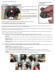
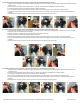
The coupler mechanism consists of 3 parts:
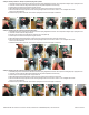
To adjust a normally closed ZC*** damper’s powered open position:
1. Detach the spring from the motor bracket. Make note of the excess spring length below the bracket. This is important in setting the proper spring return force.
2. Loosen the set screw in the Outer Ring and remove.
3. Move the screw to the boss on the right side of the Outer Arm, but do not tighten fully.
4. Rotate the plate to the intended open position using the Inner Arm.
5. While maintaining the intended plate position, rotate the Outer Arm counter-clockwise until it contacts the motor bracket.
6. Make sure that the Outer Ring is fully seated on the Inner Ring and tighten the set screw until it is ‘seated’. Do not overtighten the set screw.
Never use a powered drill driver.
7. Reattach the spring to the motor bracket. Ensure that the spring has the correct excess length as noted above.
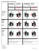
First determine which Zone Master Motorized Adjustable Damper model you have:
ZC***: Normally closed. Power-open, spring close.
ZO***: Normally open. Power-close, spring open.
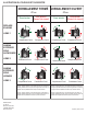
The unit is configured at the factory for 100% open and closed plate positions (see row 1 of the table on the last page). Determine if you wish to change the plate position when
powered or unpowered.
Repositioning the Outer Ring counter-clockwise will alter the plate position when powered and leave the unpowered plate position unaffected.
(See row 2 of the table on the last page).
Repositioning the Outer Ring clockwise will alter the plate position when unpowered and leave the powered plate position unaffected. (See row 3 of the table on the last page).
The extent of outer ring rotation will directly correlate to the change in plate position angle when powered or unpowered.
A ZC*** damper with more CCW Outer Ring rotation will be less open when powered and fully closed when unpowered.
A ZC*** damper with more CW Outer Ring rotation will be less closed when unpowered and fully open when powered.
A ZO*** damper with more CCW Outer Ring rotation will be less closed when powered and fully open when unpowered.
A ZO*** damper with more CW Outer Ring rotation will be less open when unpowered and fully closed when powered.
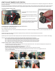
The Inner Ring with Inner Arm (2) is attached to the
damper shaft.
The Outer Ring with Outer Arm (3) can be rotated to
change the plate angle at the beginning or end of the
power cycle.
The set screw (1) locks the Outer ring in place.
The sides of each Outer and Inner Arm will contact the
motor bracket to limit the motion of the damper plate.
Unpowered position is shown in this photo.
1.
5. 6. 7.
2. 3. 4.
(1)
Set Screw
(2)
Inner Ring with Inner Arm
Proper spring location on coupler.
(3)
Outer Ring with Outer Arm
HOW TO ADJUST DAMPER PLATE POSITION