
Product Manual


Form #43219020
15 June 09
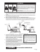
20) REPLACEMENT PARTS GUIDE
ITEM# PART # DESCRIPTION
ITEM# PART # DESCRIPTION
1 30333040 Valve VR8205A-2081 @ 10” W.C. – Propane Gas
17 43908010 Frame Assembly (1 Burner Unit)
2 30333050 Valve VR8205A-2123 @ 6” W.C. – Natural Gas
18 43908020 Frame Assembly (2 Burner Unit)
3 30279000 Transformer AT120B1051
19 43908030 Frame Assembly (3 Burner Unit)
4 30632030 Spark Module, Fenwal #35-605950-015
20 43908040 Frame Assembly (4 Burner Unit)
5 30295020 Electrode PSE-GF9
21 03548000 Junction Box, 2 x 4 x 1½
6 30314100 Ignition Cable 10”
22 03606000 Cover Plate
7 43856029 Burner Assembly Kit (Ignition Unit)
23 43849000 Ignition Control Bracket
8 43856039 Burner Assembly Kit (2
nd
, 3
rd
, and 4
th
Unit)
24 43872380 Orifice #38 for SG4, SG8, SG12, SG15 – Natural Gas
9 43862010 Manifold for SG3, SG4
25 43872410 Orifice #41 for SG10, SG14 – Natural Gas
10 43862020 Manifold for SG6, SG8
26 43872980 Orifice 3/32” for SG3, SG6 – Natural Gas
11 43862030 Manifold for SG10, SG12
27 43872520 Orifice #52 for SG3, SG6, SG10, SG13– Propane Gas
12 43862040 Manifold for SG13, SG14, SG15
28 43219020 Installation and Operation Manual (Not Shown)
13 43847010 Reflector for SG3, SG4 29 42052030 Label - Connection Wire Diagram
14 43847020 Reflector for SG6, SG8 30 42849020 Label – Nameplate
15 43847030 Reflector for SG10, SG12 31 43247030 Label – Clearances to Combustibles
16 43847040 Reflector for SG13, SG14, SG15
32 42875000 Label – General Warnings
IMPORTANT:
Please order by Part Number, not by Item Number.
Refer to complete Model Number when ordering.
All replacement parts available when ordering.
Screws, nuts and washers are standard hardware
items and can be purchased at any local hardware
store.
ALL ILLUSTRATIONS ARE INTENDED TO GIVE THE
GENERAL IMPRESSION OF UNITS ONLY. WE
RESERVE THE RIGHT TO ALTER ANY SPECIFICATION
WITHOUT NOTICE
7
8
17, 18, 19, 20
5
6
4
3
21, 22
23
1, 2
13, 14, 15, 16
9, 10, 11, 12
24, 25, 26, 27
TH
V1
GND
V2
FC+
FC-
Thermostat
R
W
24VAC
120
VAC
MV
MV
BL
W
Ignition Module
Fenwal No.
2460D
Chaud
Neutral
Ground
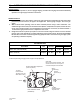
CONNECTION WIRING DIAGRAMS
chéma de circuit de connexion
TRANSFORMER
120V PRIMARY
24V SECONDARY
If any of the original wire as supplied with the
appliance must be replaced. It must be
replaced with wiring material having a
temperature rating of at least 105
o
C. (18
AWG. - UL / CSA 600V Type TEW)
When connecting the supply circuit to the
heater, wiring material having a minimum size
of 14 AWG and a temperature rating of at
least 90
o
C shall be used.
Transformateur
bobine primaire 120ÊV
bobine secondaire 24ÊV
S'il faut remplacer un fil de l'appareil d'origine,
utiliser exclusivement des fils à température
de service nominale d'au moins 105C (18
AWG. - UL / CSA 600ÊV
Type TEW).
Pour raccorder le circuit d'alimentation au
radiateur, utiliser des fils de calibre 14 AWG
ou plus à température de service nominale
d'au moins 90C.
Neutre
HIGH VOLTAGE CABLE
Haute tension
Terre
GAS VALVE
Robinet à gaz
WIRE LEGEND
ENGLISH FRANCAIS
W WHITE BLANC
R RED ROUGE
BL BLUE BLEU
G GREEN VERT
Bloc d'allumage
FACTORY WIRING
FIELD WIRING
Circuit d'origine
Connexions client
Hot
42052030
Rev. A 3/05
ELECTRODE
GAP 3/16
Écartement
d'électrode
4,7Êmm
BL
42849000 Rev. H 2/08
LIGHTING & SHUTDOWN INSTRUCTIONS
1. Turn on gas & electrical supply.
2. Set thermostat to call for heat.
3. If ignition fails, the unit will spark for approximately 21 seconds
& go into safety lockout. Turn thermostat (or power) off for 60
seconds to take out of lockout.
4. If heater does not light, shut off gas completely for 5 minutes
before attempting to relight.
5. To shut down the heater, turn off the gas & electrical supply.
INSTRUCTIONS DALLUMAGE ET DE FERMETURE
1. mettre la valve a gaz et linterrupteur a ON.
2. Creer une demande de chauffage au thermostat.
3. Si lallumage ne se fait pas, le controle dallumage continu de
produire des etincelles sur une periode de 21 sec. et ensuite
tomber en securite. Mettre le thermostat (ou le courant) en
position darret (OFF) pour une periode de 60 sec. a fin
dinterrompre le processus de securite.
4. Si lappareil ne sallume pas, fermez le gaz completement pour
une period de 5 min. avant deffectuer une nouvelle tentative
dallumage.
5. Pour fermer lappareil, fermez le gaz et le courant electrique.
UNVENTED
RADIATEUR CÉRAMIQUE À INFRAROUGES
HIGH INTENSITY INFRARED RADIANT
CERAMIC HEATER
SANS AÉRATION
ANSI Z83.19b / CSA 2.35b-2007
Gas Fired products Inc. Charlotte, NC
Tel: 1800 438 4936 e-mail info@spaceray.com
Installation in:
1. Aircraft hangers must be in accordance with the
standard for Aircraft Hangers. ANSI/NFPA 409 (latest edition).
2. Public garages must be in accordance with the standard for
parking structures, ANSI/NFPA 88a (latest edition), or with the
standard for repair garages, ANSI/NFPA 88b (latest edition)
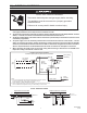
Combustible material must be located outside the clearance dimensions listed.
Failure to do so may result in death, serious injury or property damage
43247020 Rev. C 8/05
IMPORTANT!
When angle
mounting,
the control side
must be down.
Gas Valve
CEILING
FRONT
REAR
ANGLE
BELOW
SIDE
Gas Manifold
Assembly
SIDE
CEILING
BELOW
36 50 30
(91cm) (127cm) (76cm)
48 68 36
(122cm) (173cm) (91cm)
60 84 48
(145cm) (213cm) (122cm)
64 90 48
(163cm) (229cm) (122cm)
DK30, DK35, 30 36 72 100
DK33, DK40 (76cm) (91cm) (183cm) (254cm)
DK60, DK70, 48 48 98 137
DK66, DK80 (122cm) (122cm) (249cm) (348cm)
DK100, DK120 48 64 128 180
122cm) (163cm) (325cm) (457cm)
DK132, DK160, 60 64 136 190
DK140 (145cm) (163cm) (345cm) (483cm)
SIDES CEILING
w/Standard
Reflector
w/Reflector
Extension
BELOW
MODEL NO.
FRONT
REAR
w/Standard
Reflector
w/Reflector
Extension
ANGLE
MTG.
(degree)
0 min.
35 max.
0 min.
35 max.
0 min.
35 max.
10 min.
35 max.
WARNING: Improper
installation, adjustment,
alteration, service or
maintenance can cause
property damage, injury
or death. Read the
Installation, Operating
and Maintenance
Instruction thoroughly
before servicing this
equipment.
AVERTISSEMENT: Une
installation, un réglage, une
modification, une r
éparation
ou un entretien incorrect peut
entraîner des dommages
matérials, des blessures ou
la mort. Lisez attentivement
les instructions dinstallation,
de fonctionnement et
dentretien avant de procéder
à linstallation ou à lentretien
de cet équipment.
WARNING: If not
installed, operated and
maintained in accordance
with the manufacturers
instructions, this product
could expose you to
substances in fuel or from
fuel combustion which can
cause death or serious
illness and which are
known to the State of
California to cause cancer,
birth defects or other
reproductive harm.
WARNING: This product
contains a chemical known
to the state of California to
cause cancer.
This heater can be
installed in various
configurations as shown
in the heater layout
section of the instructions
42875000 Rev. E 10/04
29
30
31
32