
Product Manual

Form #43219020
7 June 09
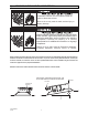
Tighten flexible gas hose and components securely.
Improperly connected gas lines may result in fire,
explosion, poisonous fumes, toxic gases, asphyxiation
or death. Connect gas lines in accordance to national,
state, provincial and local codes.
Failure to do so may result in death, serious injury or
property damage.
FIRE AND EXPLOSION HAZARD
1. Connect to the supply tank or manifold in accordance with the latest edition of National Fuel Gas Code (ANSI
Z223.1), and local building codes. Authorities having jurisdiction should be consulted before the installation
is made.
2. All gas supply lines must be located in accordance with the required clearances to combustibles below the
heater as listed on the nameplate of the heater.
3. Pipe joint compounds must be resistant to the action of liquefied petroleum gases.
4. Where local codes do not prohibit, a CSA or U.L. approved flexible connector (minimum 5/8” I.D.) is
recommended between the rigid piping and the heater. A union and an approved shut-off valve should be
installed before the control valve inlet. The shut-off valve should be installed within 6 feet of the union.
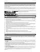
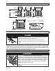
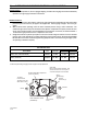
TYPICAL GAS CONNECTIONS
* Approved
Flexible Connector
*Second Stage Regulator with
Vent Leak Limiter to reduce the
Supply Pressure below 14 W.C.
Gas Pressure
= 2 PSIG
Gas Supply
Piping
Sediment Trap
(Drip Leg)
*Manual Gas
Shut Off Valve
* Available as Accessories
Alternate Supply
Location
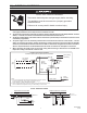
SIDE VIEW
12 (30cm)
END VIEW
Hot Gases!!
Do NOT locate gas line above
flue discharge area.
Hot Gases!!
Do NOT locate gas line above
flue discharge area.
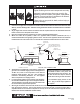
5. This appliance is equipped with a snap-opening, combination
gas valve. The maximum supply pressure to the appliance is
14” W.C. or 1/2 P.S.I. If the line pressure is more than the
maximum supply pressure, then use a line regulator as
indicated in the following illustration, or a line regulator
which corresponds to the supply pressure.
6. If a second stage regulator is used and gas seeps through it,
the redundant combination gas valve is designed to lock out.
Pressure build-up in the supply lines prior to the heater must
be released before proper heater operation.
7. After all gas connections have been made, make sure the heater and all gas outlets are turned off before the
main gas supply is turned on. Turn the gas pressure on and check for leaks. To check for leaks, apply a
soapsuds solution to all connections and joints or check by one of the methods listed in Appendix D of the
National Fuel Gas Code, ANSI Z223.1-(latest edition).
Do not use an open flame of any kind to test for leaks.
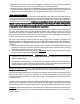
Certified connections are recommended to
be installed as shown, in one plane, and
without sharp bends, kinks or twists. The
gas take off from the drop line must be
parallel to the burner gas inlet connection.
If the maximum supply pressure is less
than ½ psig, a second stage regulator is
not required.