
Product Manual

Form #43219020
June 09 8
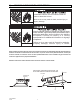
9) INSTRUCTIONS FOR PRESSURE TEST GAUGE CONNECTION
Supply Pressure
1. The installer will provide a 1/8” N.P.T. plugged tapping, accessible for test gauge connection immediately
upstream of the gas supply connection to the heater.
Manifold Pressure:
1 Turn the gas valve to the “OFF” position. Remove the 1/8” plug from the combination gas valve at the outlet
pressure tap and connect the 1/8” nipple to the tapped hole. Connect gauge to nipple. Turn on the gas
supply.
2. With the main burner operating, check the burner manifold pressure using a water manometer. The
combination gas valve is factory set and should not be adjusted. If adjustment is required, remove the cover
screw. Using a small screwdriver, turn the adjustment screw clockwise
3 to increase, or counter-clockwise 4
to decrease the gas pressure to burner. Replace the cover screw.
3. Gauges that measure in pounds per square inch are not accurate enough to measure or set the manifold
pressure. Use a water manometer or a gauge calibrated in inches of water column. All measurements MUST
BE made when this heater and all other gas burning equipment that is connected to the gas supply system
are operating at maximum capacity.
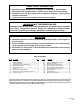
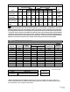
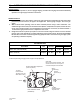
GAS PRESSURE TABLE
SUPPLY PRESSURE
HEATER MODEL
GAS
TYPE
MANIFOLD
PRESSURE
7 Minimum
Maximum
SG (3, 4, 6, 8, 10, 12, 14, 15) Natural 6” W.C. 7” W.C. 14” W.C.
SG (3, 6, 10, 13) Propane 10” W.C. 11” W.C. 14” W.C.
7 Minimum permissible gas supply pressure for purpose of input adjustment.
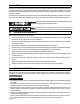
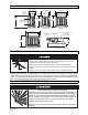
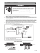
Pressure Regulator Adjustment
(under cap screw)
1/8 NPT
Inlet Pressure
Tap with 3/16 Hex
Allen Wrench Plug
1/8NPT
Outlet Pressure
Tap with 3/16
Gas Control
Knob
Wiring
Terminals (2)
Ground
Terminals (2)
OUTLET
INLET
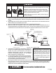
CAUTION
Never jumper these terminals. This
shorts out valve coil and may burn
out heat anticipator in thermostat.
GAS CONTROL VALVE
(#VR8205A)