INSTALLATION AND OPERATION INSTRUCTIONS OWNER / INSTALLER: For your safety this manual must be carefully and thoroughly read and understood before installing, operating or servicing this heater. STARGLO MILLIVOLT SERIES INFRARED RADIANT CERAMIC HEATER Models: SGM3, SGM6, SGM10 UNVENTED (For Indoor Installation Only) !INSTALLER: This manual is the property of the owner. Please present this manual to the owner when you leave the job site.
! WHAT TO DO IF YOU SMELL GAS: ! ! ! DO NOT try to light any appliance. Extinguish any open flame. Open windows. DO NOT touch any electrical switch. DO NOT use any telephone in your building. Immediately call your gas supplier from a neighbor’s telephone. Follow the gas supplier's instructions. If you cannot reach your gas supplier, call the Fire Department. ! SWARNING: NOT FOR RESIDENTIAL USE. This heater is not approved in any residential application.
1) SAFETY This heater is a self-contained infrared radiant ceramic heater. Safety information required during installation and operation of this heater is provided in this manual and the labels on the product. The installation, service and maintenance of this heater must be performed by a contractor qualified in the installation and service of gas fired heating equipment. All personnel in contact with the heater must read and understand all safety information, instructions and labels before operation.
! NEVER attempt to service the heater while it is plugged in, operating or hot. Any guard or other protective device removed for servicing a heater must be replaced prior to operating the heater. ! Installation and repair should be done by a qualified service person. The heater should be inspected before use and at least annually by a qualified service person. More frequent cleaning may be required as necessary.
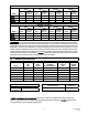
4) MINIMUM CLEARANCES TO COMBUSTIBLES Combustible material must be located outside the clearance dimensions listed. Failure to do so may result in death, serious injury or property damage. Always maintain minimum clearances and post signs where needed. Signs should state the hazards for the particular application and be legible to the building occupants. Consult the factory or a factory representative for additional information on signage compliance.
MOUNTED HORIZONTALLY BACK SIDES BACK BACK w/Reflector Extension SGM3 24” SGM6 SGM10 MODEL CEILING SIDES SIDES w/Reflector Extension 36” 24” 36” 36” 45” 48” BELOW CEILING CEILING w/Reflector Extension BELOW BELOW w/Reflector Extension 36” 24” 36” 48” 126” 30” 36” 36” 36” 72” 126” 48” 60” 36” 36” 96” 168” MOUNTED at 45º ANGLE BACK SIDES BACK BACK w/Reflector Extension SGM3 8” SGM6 SGM10 MODEL CEILING SIDES SIDES w/Reflector Extension 12” 24” 12” 12” 18” 1
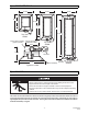
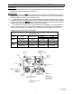
6) SGM DIMENSIONS 16-3/4 16-3/4 16-3/4 20 30-3/4 11 21-3/4 52 43-7/32 Top View SGM3 5/16 ID hole for hanging Hanging dimensions (Typical all models) (Typical 4 places) 8-3/4 10-3/8 Top View SGM6 Gas valve 16-3/4 Reflector assembly Typical End View 7) Burner assembly Top View SGM10 HANGING SUSPENSION HAZARD Always suspend from a permanent part of the building structure that can support the total force and weight of the heater.
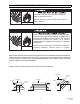
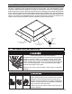
) OPTIONAL PARABOLIC REFLECTOR EXTENSION ASSEMBLY The heater is completely factory assembled and requires no field assembly. If the optional parabolic reflector extension is utilized, locate and identify the end panels and side panels as shown in the following diagram. Attach the side panels as shown. Attach the end panels so that the end flanges of the end panels overlap the side panels. Attach the side panels and end panels together with the screws provided in the kit.
1. Connect to the supply tank or manifold in accordance with the latest edition of National Fuel Gas Code (ANSI Z223.1), and local building codes. Authorities having jurisdiction should be consulted before the installation is made. (In Canada, refer to the latest edition of CAN Standard B.149-1 and -2, Installation Codes for Gas Burning Appliances and Equipment.) 2.
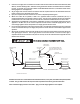
) INSTRUCTIONS FOR PRESSURE TEST GAUGE CONNECTION Supply Pressure 1. The installer will provide a 1/8" N.P.T. plugged tapping, accessible for test gauge connection immediately upstream of the gas supply connection to the heater. Manifold Pressure 1. Turn the gas valve to the "OFF" position. Remove the 1/8" plug from the manifold downstream from the combination gas valve at one of the outlet pressure taps and connect a 1/8" nipple to the tapped hole. Connect the gauge to the nipple.
) THERMOSTAT WIRING INSTALLATIONS Powerpile Thermostat * Model No. Suffix: N1, L1 Self Generating, Millivolt Standing Pilot (Single Heater Per Thermostat) Pilot Valve @ Heater TH * CAUTION: A millivolt type thermostat is required for use on self-generating pilot model heaters N1 & L1.
13) LIGHTING AND SHUTDOWN INSTRUCTIONS FIRE HAZARD Do not operate unit if repairs are necessary. Do not operate unit showing any signs of burner malfunction. Call a professional for assistance. Failure to do so may results in death, serious injury or property damage. STANDING PILOT IGNITION SYSTEM (Ignition Suffix “1”) 1) 2) 3) 4) Turn the dial to “PILOT.” Press the dial in and light the pilot. Hold for 60 seconds and release. Turn the dial counterclockwise 4 to “ON.
DO NOT DIRECT AN AIR HOSE AT THE CERAMIC EMITTER SURFACE AS IT MIGHT DAMAGE THE CERAMIC OR DISLODGE THE HIGH TEMPERATURE GASKET MATERIAL. a) b) c) d) e) Lower the heater to the floor or other suitable working surface. Remove the reflector from the reflector mounting panels or collar. Disconnect the electrode cable and flame sensor cable, or pilot burner tubing. Remove the reflector mounting panels from the heater body Remove the emitter face from the heater body.
17) REPLACEMENT PARTS GUIDE MODELS: SGM3-(N1, L1) Item No. 1 2 3 Part No. 42129000 42192000 40446080 Description Plenum Box Assembly Emitter Kit (includes items 3 & 4) End Gasket (Qty.
1 8 3,4 7 2 23 11 10 21 24 20 9 15,16 5 22 6 27-32 25 12 26 14 Combustible material must be located outside the clearance dimensions listed. Failure to do so may result in death, serious injury or property damage Controls Top Top Exhaust Vent Mount Level Exhaust Vent Back Below Controls Below Side Back Side Minimum Clearance From Combustibles Measured From Emitter Face RSCA3 Reflector Standard 43247010 Rev.
MODELS: SGM6-(N1A, L1) Item No. 1 2 3 4 5 6 7 8 9 10 11 12 14 15 16 17 18 19 20 21 22 23 24 25 26 27 28 29 30 31 32 33 34 35 36 37 Part No.
1 8 23 7 3,4 2 11 10 15,16 22 21 24 26 17 9 5 6 27-32 20 12 25 14 18,19 36 WARNING: Improper AVERTISSEMENT: Une installation, adjustment, installation, un réglage, une alteration, service or modification, une réparation maintenance can cause ou un entretien incorrect peut property damage, injury entraîner des dommages or death. Read the matérials, des blessures ou Installation, Operating la mort.
MODELS: SGM10-(N1A, L1) Item No. 1 2 3 4 5 6 7 8 9 10 11 12 13 14 15 16 19 20 21 22 23 24 25 26 27 28 29 30 31 32 33 34 35 36 37 38 39 40 41 42 43 44 45 46 47 48 49 Part No.
32 28,29,30 11 12 19,20 9 8 10 1 26 3,4 36 27 2 31 7 35 34 37 19,20 11 12 16 28,29,30 6 32 15 14 21 40-45 39 5 26 27 33 24,25 22 23 38 48 WARNING: Improper AVERTISSEMENT: Une WARNING: If not installation, adjustment, installation, un réglage, une installed, operated and alteration, service or modification, une réparation maintained in accordance maintenance can cause ou un entretien incorrect peut with the manufacturers property damage, injury entraîner des dommages instructions, t
LIMITED WARRANTY: SunStar Heating Products, Inc., the manufacturer, warrants to the original owner of any SunStar infrared gas heater that said heater will be free from defects in material or workmanship under normal use and service. The heater(s) shall be installed, used and maintained strictly in accordance with the manufacturer's instructions. The manufacturer's sole obligation under this warranty shall be limited to furnishing replacement parts, F.O.B.