
Assembly Manual

Page 3 of 4
1 Assembly
1.1 Recommended Tools
25 Watt solder iron with a screwdriver tip
Solder
Solder remover (such as solder braid)
Screwdriver
Small needle nose pliers
Multi-meter (necessary for troubleshooting and verifying operation)
Safety glasses
1.2 Assembly Sequence
Assembly order is not terribly important. The following steps assume basic soldering skills. We have
provided some basic soldering tips in the link below.
http://www.superdroidrobots.com/shop/custom.aspx/soldering-tips/23/
Tips:
Where ever possible solder joints are kept as far from traces as possible or on the top side of
the board. However, great care needs to be made to ensure excess solder is not applied and
shorts the junction to an adjacent trace. Before powering the board a close inspection needs
to be made to ensure no shorts are present.
The other common mistake is creating "dry sockets". Dry sockets will look like the solder joint
is fine, but upon closer examination the solder is only joined to the board or pin. These
connections will yield spurious behavior that is very difficult to troubleshoot. It is important that
both the board junction and the pin are heated sufficiently to allow the solder to flow and bond
the two components.
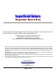
The figure on the cover shows where all the components are located on the circuit board. The
assembly sequence will require referral back this image for positioning of the electronic
components.
All the components should be placed on the top of the board (the labeled side) and soldered
from the backside.
1. Insert capacitors. The positive leg goes in the marked hole that connects to the traces. The
negative hole is connected to the ground planes. The 16V regulator goes closest to the LED. The
35V rated capacitor goes closest to the fuse.
2. Insert the 1k Ohm resistor marked R1 leading to the LED. Orientation is not important. Use the
color bands to identify the resistors resistance.
3. Insert the LED into the area marked LED1. The negative leed is marked with a line and is
connected to the resistor. The negative leg of the LED is indicated by being shorter. The base of
the negative side is also trimmed to a flat edge.
4. Insert the regulator. Orientation is important. Please refer to the individual product picture to verify.