
Blower User Manual

NOTE: DIAGRAMS & ILLUSTRATIONS NOT TO SCALE.
2
Printed in U.S.A. © 1996 by Lennox Hearth Products
P/N 903249 REV. E 11/2004
The manufacturer reserves the right to make changes at any time, without notice, in design, materials, specifications, prices and also to discontinue colors, styles and products.
Consult your local distributor for fireplace code information.
LHP
1110 West Taft Avenue
Orange, CA 92865
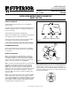
Figure 3
APPLIANCE WIRING
Most appliances are fitted with an electrical "J" box that can be
accessed from outside of the appliance outer wrapper at the time of
installation. The following general instructions apply.
WARNING: DO NOT CONFUSE BLOWER 120 VAC 60HZ
WIRING CIRCUIT WITH THE APPLIANCE LOW VOLTAGE
(MILLIVOLT) OPERATING CIRCUIT.
Step 3. Connect the ground wire to the ground screw located on the
inside of the “J” box or on the “J” box plate.
Step 4. Replace the “J” box cover back onto the side access opening
and secure with the hex head screw.
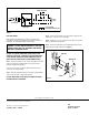
Step 5. Connect the wall switch (not provided with blower kit) to the
supply wires in the wall receptacle box (
Figure 4
).
Figure 4
CAUTION: ELECTRICAL CONNECTIONS SHOULD ONLY BE PER-
FORMED BY A QUALIFIED, LICENSED ELECTRICIAN. MAIN POWER
SUPPLY MUST BE TURNED OFF BEFORE CONNECTING FANS TO
MAIN ELECTRICAL POWER SUPPLY OR PERFORMING SERVICE.
Step 1. Remove the external "J" box cover by removing the hex-head
screw. The receptacle should be wired into an electrical circuit
during the framing of the appliance.
The “J” box cover has a 7/8" (22mm) diameter knockout hole for
connection of a conduit bushing.
Step 2. Wire with minimum 60
0
C wire in accordance with prevailing
codes. The blower draws 1 amp at 120 Vac 60Hz.
CAUTION: MAIN POWER SUPPLY MUST BE TURNED OFF BEFORE
EXTERNAL WIRING IS PERFORMED.
NOTE: DIAGRAMS & ILLUSTRATIONS NOT TO SCALE.
Factory Supplied
Not Supplied with Blower Kit
Blower Plug
Junction Box
ON/OFF Wall Switch
120Vac
60Hz
}
Switch Plate
Wall Box
Switch
Black Black
Neutral
White
Supply
To Blower