SUPER ® SC216 CHASSIS Series SC216A-R1200UB SC216A-R1200LPB SC216A-R900UB SC216A-R900LPB SC216E1-R900LPB SC216E2-R900LPB SC216E1-R900UB SC216E2-R900UB USER’S MANUAL 1.
SC216 Chassis Manual The information in this User’s Manual has been carefully reviewed and is believed to be accurate. The vendor assumes no responsibility for any inaccuracies that may be contained in this document, makes no commitment to update or to keep current the information in this manual, or to notify any person or organization of the updates. Please Note: For the most up-to-date version of this manual, please see our web site at www.supermicro.com. Super Micro Computer, Inc.
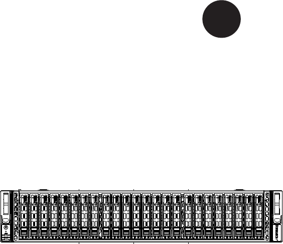
Preface Preface About This Manual This manual is written for professional system integrators and PC technicians. It provides information for the installation and use of the SC216 2U chassis. Installation and maintenance should be performed by experienced technicians only. Supermicro’s SC216 maximizes storage capacity in a 2U form factor by offering 24 hot-swappable 2.5” SAS/SATA hard drive bays for applications requiring extra storage.
SC216 Chassis Manual Manual Organization Chapter 1 Introduction The first chapter provides a checklist of the main components included with this chassis and describes the main features of the SC216 chassis. This chapter also includes contact information. Chapter 2 System Safety This chapter lists warnings, precautions, and system safety.
Preface Appendices This section lists compatible cables, power supply specifications, and compatible backplanes. Not all compatible backplanes are listed. Refer to our Web site for the latest compatible backplane information at http://www.supermicro.
SC216 Chassis Manual Table of Contents Chapter 1 Introduction 1-1 Overview.......................................................................................................... 1-1 1-2 Shipping List..................................................................................................... 1-1 1-3 Contacting Supermicro..................................................................................... 1-2 1-4 Returning Merchandise for Service............................................
Preface Motherboard Installation................................................................................... 5-7 5-6 Installing the Add-on Cards.............................................................................. 5-8 Installing Add-on Cards in Low-Profile Model Chassis.................................... 5-8 Installing Riser Cards and Add-on Cards in UIO Models................................ 5-9 5-7 Installing the Air Shrouds.............................................................
SC216 Chassis Manual Notes viii
Chapter 1: Introduction Chapter 1 Introduction 1-1 Overview Supermicro’s SC216 2U chassis features a unique and highly-optimized design. The chassis is equipped with high efficiency power supply. 1-2 Shipping List Please visit the following link for the latest shipping lists and part numbers for your particular chassis model http://www.supermicro.com/products/chassis/2U/ ?chs=216 SC216 Chassis CPU HDD I/O Slots Power Supply SC216A-R1200UB Single/Dual CPU 24x 2.
SC216 Chassis Manual 1-3 Contacting Supermicro Headquarters Address: Super Micro Computer, Inc. 980 Rock Ave. San Jose, CA 95131 U.S.A. Tel: +1 (408) 503-8000 Fax: +1 (408) 503-8008 Email: marketing@supermicro.com (General Information) support@supermicro.com (Technical Support) Web Site: www.supermicro.com Europe Address: Super Micro Computer B.V. Het Sterrenbeeld 28, 5215 ML 's-Hertogenbosch, The Netherlands Tel: +31 (0) 73-6400390 Fax: +31 (0) 73-6416525 Email: sales@supermicro.
Chapter 1: Introduction 1-4 Returning Merchandise for Service A receipt or copy of your invoice marked with the date of purchase is required before any warranty service will be rendered. You can obtain service by calling your vendor for a Returned Merchandise Authorization (RMA) number. When returning to the manufacturer, the RMA number should be prominently displayed on the outside of the shipping carton, and mailed prepaid or hand-carried.
SC216 Chassis Manual Notes 1-4
Chapter 2: System Safety Chapter 2 System Safety 2-1 Overview This chapter provides a quick setup checklist to get your chassis up and running. Following the steps in order given should enable you to have your chassis setup and operational within a minimal amount of time. This quick set up assumes that you are an experienced technician, familiar with common concepts and terminology.
SC216 Chassis Manual 2-4 Electrical Safety Precautions Basic electrical safety precautions should be followed to protect yourself from harm and the SC216 from damage: • • • • • • • • Be aware of the locations of the power on/off switch on the chassis as well as the room’s emergency power-off switch, disconnection switch or electrical outlet. If an electrical accident occurs, you can then quickly remove power from the system. Do not work alone when working with high voltage components.
Chapter 2: System Safety • DVD-ROM Laser: CAUTION - this server may have come equipped with a DVD-ROM drive. To prevent direct exposure to the laser beam and hazardous radiation exposure, do not open the enclosure or use the unit in any unconventional way. 2-5 • • • • • 2-6 General Safety Precautions Keep the area around the chassis clean and free of clutter.
SC216 Chassis Manual • • • • • • Touch a grounded metal object before removing any board from its antistatic bag. Do not let components or PCBs come into contact with your clothing, which may retain a charge even if you are wearing a wrist strap. Handle a board by its edges only; do not touch its components, peripheral chips, memory modules or contacts. When handling chips or modules, avoid touching their pins. Put the serverboard and peripherals back into their antistatic bags when not in use.
Chapter 3: Chassis Components Chapter 3 Chassis Components 3-1 Overview This chapter describes the most common components included with your chassis. Some components listed may not be included or compatible with your particular chassis model. For more information, see the installation instructions detailed later in this manual. 3-2 Components Chassis The chassis includes three hard drive bays, which support twenty-four 2.5" hard drives. The hard drives must be purchased separately.
SC216 Chassis Manual Power Supply Each SC216 chassis model includes a high-efficiency redundant power supply rated at 900 or 1200 Watts. In the unlikely event your power supply fails, replacement is simple and can be done without tools. Air Shroud Air shrouds are shields, usually plastic, that funnel air directly to where it is needed. Always use the air shroud included with your chassis. 3-3 Where to get Replacement Components Though not frequently, you may need replacement parts for your system.
Chapter 4: System Interface Chapter 4 System Interface 4-1 Overview The control panel features an LED display, and the individual drive carriers also feature LEDs. These LEDs keep you constantly informed of the overall status of the system, and monitor the activity and health of specific components. SC216 models feature two buttons on the chassis control panel, an on/off button and a reset button. This chapter explains the meanings of all LED indicators and the appropriate responses you may need to take.
SC216 Chassis Manual 4-2 Control Panel Buttons There are two push-buttons located on the front of the chassis. These are a power on/off button and a reset button. • • 4-3 Power: The main power switch is used to apply or remove power from the power supply to the server system. Turning off system power with this button removes the main power but keeps standby power supplied to the system. Therefore, you must unplug system before servicing. Reset: The reset button is used to reboot the system.
Chapter 4: System Interface • NIC2: Indicates network activity on GLAN2 when flashing. • NIC1: Indicates network activity on GLAN1 when flashing. ! • • Power Failure: When this LED flashes, it indicates a power failure in the power supply. Overheat/Fan Fail: When this LED flashes it indicates a fan failure. When continuously on (not flashing) it indicates an overheat condition, which may be caused by cables obstructing the airflow in the system or the ambient room temperature being too warm.
SC216 Chassis Manual 4-4 Drive Carrier LEDs The SC216 chassis supports SAS/SATA drives. SAS/SATA Drives Each SAS/SATA drive carrier has two LEDs. • • Green or Blue: Each hard disk drive carrier has either a green or a blue LED, depending upon the hard disk drives and backplane used. When illuminated, this LED indicates drive activity. A connection to the SATA backplane enables this LED to blink on and off when that particular drive is being accessed. .
Chapter 5: Chassis Setup and Maintenance Chapter 5 Chassis Setup and Maintenance 5-1 Overview This chapter covers the steps required to install components and perform maintenance on the chassis. The only tool required to install components and perform maintenance is a Phillips screwdriver. Print this page to use as a reference while setting up your chassis.
SC216 Chassis Manual 5-3 Removing the Chassis Cover 3 1 1 2 Remove this screw (if necessary) Release Tab Figure 5-1: Removing the Chassis Cover Removing the Chassis Cover 1. Press the release tabs to remove the cover from the locked position. Press both tabs at the same time. 2. Once the top cover is released from the locked position, slide the cover toward the rear of the chassis. 3. Lift the cover off the chassis.
Chapter 5: Chassis Setup and Maintenance 5-4 Installing Hard Drives 2 1 Figure 5-2: Removing Hard Drive The SC216 comes equipped with twenty-four hot-swappable hard drives. Only SAS or enterprise SATA HDDs are recommended for use in the SC216 chassis. Removing Hard Drive Trays from the Chassis 1. Press the release button on the drive tray. This extends the drive bay handle. 2. Use the handle to pull the tray out of the chassis.
SC216 Chassis Manual Figure 5-3: Hard Drive Tray Installing a Hard Drive into a Drive Carrier 1. Insert a drive into the carrier with the PCB side facing down and the connector end toward the rear of the carrier. 2. Align the drive in the carrier so that the mounting holes of both are aligned. Note that there are holes in the carrier marked "SAS" or “SATA” to aid in correct installation. 3. Secure the drive to the carrier with four screws as illustrated above.
Chapter 5: Chassis Setup and Maintenance I/O Shield Figure 5-5: I/O Shield Placement 5-5 Installing the Motherboard I/O Shield The I/O shield holds the motherboard ports in place. Install the I/O shield before installing the motherboard. If the motherboard you purchased did not include a standard I/O shield, contact the motherboard vendor for a compatible shield. Installing the I/O Shield 1. Review the documentation that came with your motherboard.
SC216 Chassis Manual Permanent and Optional Standoffs Standoffs prevent short circuits by securing space between the motherboard and the chassis surface. The SC216 chassis includes permanent standoffs in locations used by most motherboards. These standoffs accept the rounded Phillips head screws included in the SC216 accessories packaging. Some motherboard require additional screws for heatsinks, general components and/or non-standard security. Optional standoffs are included for these motherboards.
Chapter 5: Chassis Setup and Maintenance Motherboard Installation Installing the Motherboard 1. Review the documentation that came with your motherboard. Become familiar with component placement, requirements, precautions, and cable connections. 2. Open the chassis cover. 3. If necessary, remove the air shroud and riser card bracket. 4. Ensure that the I/O shield has been installed correctly. 5.
SC216 Chassis Manual 5-6 Installing the Add-on Cards Add-on card installation in the SC216 chassis differs between the UIO and lowprofile chassis models. See below for directions that are specific you your chassis type. Installing Add-on Cards in Low-Profile Model Chassis Installing Add-on Cards - Low-Profile Chassis Models 1. Remove the chassis cover and ensure that the motherboard has been properly installed. 2. Locate the vertical add-on card slots in the rear of the SC216 chassis. 3.
Chapter 5: Chassis Setup and Maintenance Secure the tail of the riser card bracket to the fan tray with one screw Secure the head of the riser card bracket to the rear of the chassis with two screws Figure 5-9: Installing the UIO Riser Card Bracket Installing Riser Cards and Add-on Cards in UIO Models Installing the Riser Card - UIO Chassis Models 1. Remove the chassis cover. 2. Remove the riser bracket. 3. Install the riser card onto the riser bracket.
SC216 Chassis Manual Figure 5-10: UIO Add-on Card Installed Installing the Add-on Cards in UIO Chassis Models 1. Ensure that the riser card and riser card bracket have been correctly installed in the chassis. 2. Remove the blank bracket from the rear slot in the chassis. 3. Slide the add-on card horizontally into the slot on the riser card. 4. Secure the add-on-card with its clip into the rear slot of the chassis.
Chapter 5: Chassis Setup and Maintenance 5-7 Installing the Air Shrouds Figure 5-11: Installing the Air Shroud Air shrouds concentrate airflow to maximize fan efficiency. The SC216 chassis air shroud does not require screws for installation. Installing the Air Shroud in the Chassis Installing the Air Shroud 1. Lay the chassis on a flat, stable surface and remove the chassis cover. 2. Ensure that the motherboard, CPU, heatsink and memory are all properly installed. 3.
SC216 Chassis Manual 13 12 Figure 5-12: Installing the Additional Air Shroud An additional air shroud is required for high-powered CPUs, to provide extra cooling. Install the additional air shroud if necessary. Installing the Additional Air Shroud Installing the Additional Air Shroud in the Chassis 1. Remove the left side break-away piece of the main air shroud. 2. Slide the additional air shroud into the chassis before installing the main air shroud. 3.
Chapter 5: Chassis Setup and Maintenance 5-8 Checking the Air Flow Checking the Server's Air Flow 1. Make sure there are no objects to obstruct airflow in and out of the server. In addition, if you are using a front bezel, make sure the bezel's filter is replaced periodically. 2. Do not operate the server without drives or drive trays in the drive bays. Use only recommended server parts. 3. Make sure no wires or foreign objects obstruct air flow through the chassis.
SC216 Chassis Manual 5-9 System Fans Three heavy duty fans provide cooling for the chassis. These fans circulate air through the chassis as a means of lowering the chassis internal temperature. The SC216 fans are hot-swappable, enabling the fans to be replaced without powering -down the system. Release Tab Figure 5-13: System Fan Replacing a System Fan 1. If necessary, open the chassis while the power is running to determine which fan requires changing.
Chapter 5: Chassis Setup and Maintenance Figure 5-14: Placing the System Fan 5-15
SC216 Chassis Manual 5-10 Power Supply The SC216 chassis has two redundant 900 Watt power supplies. The power modules are hot-swappable, enabling the power supplies to be changed without powering down the system. These power supplies are auto-switching capable. This enables the power supply to automatically sense and operate at a 100v to 240v input voltage. An amber light will be illuminated on the power supply when the power is off. An illuminated green light indicates that the power supply is operating.
Chapter 5: Chassis Setup and Maintenance 4. Replace the failed power module with the same model power supply. 5. Push the new power supply module into the power bay until the tab clicks into the locked position. 6. Plug the AC power cord back into the module and the replacment power module will automatically power-up.
SC216 Chassis Manual Figure 5-16: Replacing the Power Distributor Power Distributor The power distributor provides failover and power supply redundancy, and is pre-installed in the chassis. In the rare event that you have to replace the power distributor, follow the steps below. Changing the Power Distributor 1. Power down the server and unplug the power cord from the power module. 2. Remove all cable connections to the power supply from the motherboard, backplane, and other components.
Chapter 5: Chassis Setup and Maintenance 5-11 Removing the Backplane The SC216 chassis backplane is located behind the hard drives and in front of the front system fans. In order to change jumper settings on the backplane, it may be necessary to remove the backplane from the chassis. Removing the Backplane from the Chassis 1. Power down and unplug the system from any power source. 2. Remove the chassis cover. 3. Disconnect the cabling to the backplane. 4.
SC216 Chassis Manual 6. Loosen the three screws in the spring bar, located on the floor of the chassis, indicated by the arrows below. 6 Figure 5-18: Loosening the Spring Bar Screws in the Floor of the Chassis 7. Gently ease the backplane up and out of the chassis.
Chapter 5: Chassis Setup and Maintenance 5-12 Installing the Backplane Installing the Backplane into the Chassis 1. Ensure that all of the hard drive trays have been removed from the bays in the front of the chassis and that the spring bar has been loosened as directed in the previous section. 2. Slide the backplane into the chassis at a slight angle, pushing it up against the side of the chassis. 3. Ease the backplane forward, against the front of the chassis.
SC216 Chassis Manual Notes 5-22
Chapter 6: Rack Installation Chapter 6 Rack Installation 6-1 Overview This chapter provides a quick setup checklist to get your chassis up and running. Following these steps in the order given should enable you to have the system operational within a minimal amount of time. 6-2 Unpacking the System You should inspect the box which the chassis was shipped in and note if it was damaged in any way. If the chassis itself shows damage, you should file a damage claim with the carrier who delivered it.
SC216 Chassis Manual ! 6-4 • Warning! ! Warnings and Precautions Rack Precautions Ensure that the leveling jacks on the bottom of the rack are fully extended to the floor with the full weight of the rack resting on them. • In single rack installations, stabilizers should be attached to the rack. • In multiple rack installations, the racks should be coupled together. • • • • • • • Always make sure that the rack is stable before extending a component from the rack.
Chapter 6: Rack Installation • 6-5 Always keep the rack's front door and all panels and components on the servers closed when not servicing to maintain proper cooling. Rack Mounting Considerations Ambient Operating Temperature If installed in a closed or multi-unit rack assembly, the ambient operating temperature of the rack environment may be greater than the ambient temperature of the room.
SC216 Chassis Manual 6-6 Rack Mounting Instructions This section provides information on installing the chassis into a rack unit with the rails provided. There are a variety of rack units on the market, which may mean that the assembly procedure will differ slightly from the instructions provided. You should also refer to the installation instructions that came with the rack unit you are using. NOTE: This rail will fit a rack between 26.5" and 36.4" deep.
Chapter 6: Rack Installation Locking Tabs Each inner rail has a locking tab. This tab locks the chassis into place when installed and pushed fully into the rack. These tabs also lock the chassis in place when fully extended from the rack. This prevents the server from coming completely out of the rack when when the chassis is pulled out for servicing. Releasing the Inner Rail Releasing Inner Rail from the Outer Rails 1. Identify the left and right outer rail assemblies as described on page 6-4. 2.
SC216 Chassis Manual Inner Rails 14 2 14 3 Figure 6-3: Installing the Inner Rails Figure 6-4: Inner Rails Installed on the Chassis (The chassis above are an example only. Actual chassis may differ slightly) Installing The Inner Rails on the Chassis Installing the Inner Rails 1. Confirm that the left and right inner rails have been correctly identified. 2. Place the inner rail firmly against the side of the chassis, aligning the hooks on the side of the chassis with the holes in the inner rail. 3.
Chapter 6: Rack Installation 1 L-min=676.00(26.61")(outer rail) 12 14 21D01 13 Figure 6-5: Extending and Releasing the Outer Rails Installing the Outer Rails on the Rack Installing the Outer Rails 1. Press upward on the locking tab at the rear end of the middle rail. 2. Push the middle rail back into the outer rail. 3. Hang the hooks of the front of the outer rail onto the slots on the front of the rack. If necessary, use screws to secure the outer rails to the rack, as illustrated above. 4.
SC216 Chassis Manual Ball-Bearing Shuttle Figure 6-6: Installing into a Rack Standard Chassis Installation Installing the Chassis into a Rack 1. Confirm that the inner rails are properly installed on the chassis. 2. Confirm that the outer rails are correctly installed on the rack. 3. Pull the middle rail out from the front of the outer rail and make sure that the ball-bearing shuttle is at the front locking position of the middle rail. 4. Align the chassis inner rails with the front of the middle rails.
Chapter 6: Rack Installation Optional Quick Installation Method The following quick installation method may be used to install the chassis onto a rack. Installing the Chassis into a Rack 1. Install the whole rail assembly onto the rack as described on page 6-7. 2. Release the inner rail without retracting the middle rail. 3. Install the inner rails on the chassis as previously described on page 6-6. 4. Install the chassis onto the middle rail as described in the previous section.
SC216 Chassis Manual Notes 6-10
Appendix A: Chassis Cables Appendix A SC216 Chassis Cables A-1 Overview This appendix lists supported cables for your chassis system. It only includes the most commonly used components and configurations. For more compatible cables, refer to the manufacturer of the motherboard you are using and our Web site at: www.supermicro.com.
SC216 Chassis Manual A-3 Compatible Cables These cables are compatible with the SC216 Chassis. Alternate SAS/SATA Cables Some compatible motherboards have different connectors. If your motherboard has only one SAS connector that the SAS/SATA cables must share, use one of the following cables. These cables must be purchased separately. Cable Name: SAS Cable Quantity: 1 Part #: CBL-0175L Alt.
Appendix A: Chassis Cables Extending Power Cables Although Super Micro chassis are designed to be efficient and cost-effective, some compatible motherboards have power connectors located in different areas. To use these motherboards you may have to extend the power cables to the mother boards. To do this, use the following chart as a guide. Power Cable Extenders Number of Pins Cable Part # Length 24 pin CBL - 0042 7.9”(20 CM) 20 pin CBL - 0059 7.9”(20 CM) 8 pin CBL - 0062 7.
SC216 Chassis Manual Notes A-4
Appendix B: Power Supply Specifications Appendix B SC216 Power Supply Specifications This appendix lists power supply specifications for the SC216 chassis. SC216A-R900UB, SC216A-R900LPB SC216E1-R900LPB, SC216E2-R900LPB SC216E1-R900UB, SC216E2-R900UB 900W MFR Part # PWS-902-1R with PDB Rated AC Voltage 100 - 240V 60 - 50Hz 11 - 4.5 Amp +5V standby 4 Amp +12V 75 Amp +5V 45 Amp +3.3V 24 Amp -12V 0.
SC216 Chassis Manual Notes B-2
Appendix C: SAS-216A Backplane Specifications Appendix C SAS-216A Backplane Specifications To avoid personal injury and property damage, carefully follow all the safety steps listed below when accessing your system or handling the components. C-1 ESD Safety Guidelines Electrostatic Discharge (ESD) can damage electronic components. To prevent damage to your system, it is important to handle it very carefully. The following measures are generally sufficient to protect your equipment from ESD.
SC216 Chassis Manual C-3 A Note to Users • All images and layouts shown in this user's guide are based upon the latest PCB Revision available at the time of publishing. The card you have received may or may not look exactly the same as the graphics shown in this manual. C-4 Introduction to the SAS-216A Backplane The SAS-216A backplane has been designed to utilize the most up-to-date technology available, providing your system with reliable, high-quality performance.
Appendix C: SAS-216A Backplane Specifications Jumper Settings and Pin Definitions C-5 Front Connectors and Jumpers JSM6 6 13 SAS IN#6 5 12 R282 R283 JP95 I2C#2 A1 + JP36 1 1 C139 BZ1 1 + + + 8 4 C327 1 JP48 8 4 C244 C253 C239 + JP109 1 JP46 4 8 C201 + 1 C197 + + C323 C220 C153 C294C295 1 JP13 8 4 1 JP10 4 C6 C47 C5 D4 D9 C A D9:ALARM#3 D3 R6 8 4 B1 R7 JP110 6 R8 1 C224 U30 C420 C24 C157 5 I2C#3 U91 R608 U88 C399 JP80 C297 C298
SC216 Chassis Manual C-6 Front Connector and Pin Definitions 1. Upgrade Connectors The upgrade connectors are designated JP69, JP78 and JP115 are used for manufacturer's diagnostic purposes only. 2. - 7. I2C Connectors I2C Connector Pin Definitions (JP37, JP95, JP52, JP96, JP115 and JP116 The I C Connectors, designated JP37, JP95, JP52, JP96, JP115 and JP116 are used to monitor HDD activity and status. See the table on the right for pin definitions. 2 Pin# Definition 8.
Appendix C: SAS-216A Backplane Specifications C-7 Front Jumper Locations and Pin Definitions SAS IN#6 16 U53 SAS IN#4 SAS IN#5 C280 C250 R431 R287 SAS IN#3 R282 R283 JP95 I2C#2 A1 + JP36 1 C139 BZ1 JP52 R608 U88 C399 JP80 18 + + + C327 1 JP48 4 C244 C253 C239 + 4 1 JP46 C201 4 + JP109 C197 + 1 C220 C153 C294C295 1 JP13 4 1 JP10 4 C6 C47 C5 D4 D9 C A D9:ALARM#3 D3 R6 + C323 C224 R7 4 B1 R8 JP110 6 U30 1 5 I2C#3 U91 C415 C420 3 JP84 JS
SC216 Chassis Manual I2C and SGPIO Modes and Jumper Settings This backplane can utilize I2C or SGPIO. SGPIO is the default mode and can be used without making changes to your jumper. The following information details which jumper must be configured to use SGPIO mode or restore your backplane to I2C mode.
Front LED Indicators + JSM6 SAS IN#6 U53 SAS IN#4 SAS IN#5 C280 C250 R431 R287 R430 SAS IN#3 C44 SAS IN#2 BAR CODE R283 JP95 I2C#2 A1 + R281 R286 JP96 R280 JP36 1 + 2 1 C212 C139 Y2 BZ1 3 3 C383 R585 JP52 3 JP84 JSM2 JSM3 R365 C213 JP117 JP36 9072#2 RST 1-2:RST 2-3:NO RST JSM4 1 R432 C247 R268 R267 3 JSM5 C249 C246 R273 I2C#4 1 REV: 1.
SC216 Chassis Manual C-8 Rear Components, Connectors and LED Indicators 1 16 16 U24 C100 C102 U66 C359 48 48 33 RP6 J44 J36 J20 J11 J45 J34 J9 J31 J43 J18 J4 J33 J28 J3 J17 J15 J37 J2 J35 J21 J1 J13 7 27 7 27 7 27 7 27 7 27 7 27 7 27 7 27 7 27 7 27 7 27 7 27 7 27 7 27 7 27 7 27 7 27 7 27 7 27 7 27 7 27 7 27 7 27 7 27 33 33 8 9 8 9 33 8 9 33 8 9 33 8 9 33 8 9 9 33 8 9 33 8 33 8 9 33 8 9 33 8 9 33 8 9 33 8 9 33 8 9 33 8 9 33 8 9 33 8 9
Appendix C: SAS-216A Backplane Specifications Rear LED Indicators Hard Drive Activity Failure LED SAS #0 Rear LED D12 D5 SAS #1 D22 D23 SAS #2 D40 D37 SAS #3 D102 D107 SAS #4 D13 D6 SAS #5 D24 D29 SAS #6 D41 D38 SAS #7 D104 D108 SAS #8 D14 D7 SAS #9 D25 D30 SAS #10 D42 D39 SAS #11 D106 D109 SAS #12 D15 D8 SAS #13 D26 D31 SAS #14 D87 D88 SAS #15 D111 D110 SAS #16 D18 D19 SAS #17 D27 D32 SAS #18 D100 D103 SAS #19 D118 D119 SAS #20 D21 D20 SAS #
SC216 Chassis Manual Notes C-10
Appendix D: SAS-216EL Backplane Specifications Appendix D SAS-216EL Backplane Specifications D-1 Overview of the SAS-216EL1/EL2 Backplanes The SAS-216EL1/EL2 series of backplanes consists of a SAS-216EB backplane (A) with one or two SAS-216EL daughter cards (B and C) mounted on the rear of the backplane. The SAS-216EL1 model consists of the SAS-216EB backplane (A) and one SAS216EL daughter card (C), mounted on the right-hand side of the backplane.
SC213 Chassis Manaual Safety Guidelines To avoid personal injury and property damage, carefully follow all the safety steps listed below when accessing your system or handling the components. D-1 ESD Safety Guidelines Electrostatic Discharge (ESD) can damage electronic components. To prevent damage to your system, it is important to handle it very carefully. The following measures are generally sufficient to protect your equipment from ESD. Use a grounded wrist strap designed to prevent static discharge.
Appendix D: SAS-216EL Backplane Specifications Introduction to the SAS-216EL Backplane The SAS-216EL backplane has been designed to utilize the most up-to-date technology available, providing your system with reliable, high-quality performance. This manual reflects SAS-216EL Revision 1.01, the most current release available at the time of publication. Always refer to the Supermicro Web site at www.supermicro. com for the latest updates, compatible parts and supported configurations.
+ + BC50 BC91 BC82 BC54 BC55 BC81 BC87 BC51 +12V GND GND BC83 +5V +12V BC72 C133 C130 C105 C103 C120 C118 C127 C124 C106 C98 C126 C123 C132 C129 C138 C135 C146 C166 C88 C107 C111 C90 C113 C94 C162 C159 C158 C157 C155 C172 C153 C168 L28 L10 L17 L15 L34 L32 L41 L51 L47 L43 L40 WWN GND GND R72 C339 R104 C171 R8 BC2 C326 C327 C340 L3 L65 L58 L55 L52 L50 L46 L45 L39 L69 L68 L62 L67 L61 L60 L59 L66 L25 L23 L8 L6 R105 R88 C337 R106 R108 R75 C349 C343 C341 C344 C342 C345 C3
SC213 Chassis Manaual D-5 Rear Connector and Pin Definitions 1. Primary Flash Chips The Primary Flash Chip enhances the backplane memory. 2. Expander Chips This Expander Chip allows the backplane to support dual ports, cascading, and failover. 3. - 5. SAS Ports The primary and secondary sets of SAS ports provide expander features including cascading and failover From right to left the ports are Primary 1/2/3 and Secondary 1/2/3. 6.
+ + + C142 GND GND + +5V +12V GND GND 64 +12V + + + +5V +12V GND +12V GND +5V GND GND +5V +12V GND GND 2 +5V +5V + GND + BC50 BC58 BC60 + BC62 + + BC64 BC53 BC74 BC70 BC76 BC65 BC78 BC68 + BC86 BC90 BC92 + + + + + + + BC91 BC82 C117 BC54 BC55 BC81 BC87 BC51 BC83 BC2 BC1 EC5 EC11 BC72 C48 C48 EC5 BC2 BC1 63 BC96 BC10 BC49 BC67 + C95 BC84 + BC96 BC10 BC12 BC5 + BC13 BC18 BC14 BC20 + + + EC11 C171 R8 + BC2 BC36 BC22 BC26
SC213 Chassis Manaual General Jumper Settings Jumper Jumper Settings Note PRI_MODE1 1-2 Factory Setting Do not change BUZZER_ENB1 Open: Disable Closed: Enable Buzzer Enable* Socket Settings Socket REMOTE_FAN_FAIL_ SOCKET1 Socket Setting Note Front Panel Fan Fail indicator (Optional) Connected Front Panel LEDs LED State Specification 12V_LED1 OFF Backplane power failure. Light is on during normal operation. 5V_LED1 OFF Backplane power failure. Light is on during normal operation.
Appendix D: SAS-216EL Backplane Specifications SAS SAS SAS SAS SAS SAS SAS SAS SAS SAS SAS SAS SAS SAS SAS SAS SAS SAS SAS SAS SAS SAS SAS SAS #J0 #J1 #J2 #J3 #J4 #J5 #J6 #J7 #J8 #J9 #J10 #J11 #J12 #J13 #J14 #J15 #J16 #J17 #J18 #J19 #J20 #J21 #J22 #J23 D-7 Front Connectors and LED Indicators BPN-SAS216EB MH4 MH3 MH7 MH6 MH8 BAR CODE Rev:1.
SC213 Chassis Manaual Front LED Indicators Hard Drive Activity Failure LED SAS #J0 Front LED ACT #1 FAIL #1 SAS #J1 ACT #2 FAIL #2 SAS #J2 ACT #3 FAIL #3 SAS #J3 ACT #4 FAIL #4 SAS #J4 ACT #5 FAIL #5 SAS #J5 ACT #6 FAIL #6 SAS #J6 ACT #7 FAIL #7 SAS #J7 ACT #8 FAIL #8 SAS #J8 ACT #9 FAIL #9 SAS #J9 ACT #10 FAIL #10 SAS #J10 ACT #11 FAIL #11 SAS #J11 ACT #12 FAIL #12 SAS #J12 ACT #13 FAIL #13 SAS #J13 ACT #14 FAIL #14 SAS #J14 ACT #15 FAIL #15 SAS #J15 ACT #1
Appendix D: SAS-216EL Backplane Specifications D-8 Front Connectors and Jumpers Front Components 1.
SC213 Chassis Manaual Dual Port and Cascading Configurations D-9 Single and Dual Port Expanders Single Ports SAS-216EL1 backplanes have a single-port expander on the daughter card, that accesses all 24 drives and supports cascading.
Appendix D: SAS-216EL Backplane Specifications D-10 Failover The SAS-216EL2 backplane has two expanders which allow effective failover and recovery.
SC213 Chassis Manaual D-11 Chassis Power Card and Support Cables Chassis Power Card In a cascaded configuration, the first chassis includes a motherboard and at least one Host Bus Adapter (HBA). Other servers in this enclosed system, include a power card. This section describes the supported power card for the SAS-216 series backplane. For more information, see the Supermicro Web site at http://www.supermicro. com. A A A JBPWR2 REV 1.
Appendix D: SAS-216EL Backplane Specifications Connectioning an Internal Host Bus Adapter to the Backplane The following section lists the most common cables used to connect the Host Bus Adapter (HBA) to the backplane.
SC213 Chassis Manaual Cable Name: IPASS (mini SAS) TO IPASS (mini SAS) Part #: CBL-0108L-02 Length: 39 cm (15 inches) Part #: CBL-0109L-02 Length: 22 cm (9 inches) Part #: CBL-0110L-02 Length: 18 cm (7 inches) Description: This cable has an ipass (SFF-8087/mini-sas) connector (36 pins) at each end. It connects from the HBA to the SAS-216EL backplane.
Appendix D: SAS-216EL Backplane Specifications Connecting an External Host Bus Adapter to the Backplane This backplane supports external Host Bus Adapters. In this configuration, the HBA and the backplane are in different physical chassis. This allows a JBOD (Just a Bunch Of Drives) configuration from an existing system.
SC213 Chassis Manaual Supported External HBA to Backplane Cable Use the following cable if your external HBA has an InfiniBand connector. Figure D-16: SAS InfiniBand Cable (CBL-0200L) Cable Name: SAS InfiniBand to Mini SAS X4 1M cable, PBF Part #: CBL-0200L Length: 1 meter Description: This cable has an InfiniBand connector (SFF-8470) on one end and an SFF-8088-1X (26-pins) at the other end.
Appendix D: SAS-216EL Backplane Specifications Connecting Multiple Backplanes in a Single Channel Environment This section describes the cables used when cascading from a single HBA. These connections use CBL-0167L internal cables and CBL-0166L external cables.
SC213 Chassis Manaual Single HBA Configuration Cables Single Port Cable Assembly Figure D-18: Single Port Internal Cable (CBL-0167L) Cable Name: SAS EL2/EL1 Backplane Cable (Internal) with 2-port Cascading Cable, 68 cm Part #: CBL-0167L (SFF-8087 to SFF-8088 x1) Ports: Single Placement: Internal cable Description: Internal cable. Connects the backplane to the Host Bus Adapter (HBA) or external port.
Appendix D: SAS-216EL Backplane Specifications Connecting Multiple Backplanes in a Dual Channel Environment This section describes the cables used when cascading from dual HBAs. These connections use CBL-0168L internal cables and CBL-0166L external cables.
SC213 Chassis Manaual Dual HBA Configuration Cables Dual Port Cable Assembly Figure D-21: Dual Port Internal Cable (CBL-0168L) Cable Name: SAS Dual-port Cable Assembly, 68/76cm Part #: CBL-0168L Placement: Internal cable Ports: Dual Description: Internal cascading cable. Connects the backplane to the Host Bus Adapter (HBA) or external port. Used in dual port environments.
Appendix D: SAS-216EL Backplane Specifications Supported Cascading Configurations D-12 Cascading allows the system to access data at a faster rate by allowing several backplanes to share resources to reduce latency time. The first backplane in a cascaded system requires a motherboard and HBA. Other servers require a power control card with no motherboard and no HBA. For more information, see the SC216 Chassis Manual available at www.supermicro.com.
SC213 Chassis Manaual Server System with Single SAS HBA The expanders allow horizontal branching. This configuration also applies to dual ports.
Appendix D: SAS-216EL Backplane Specifications Dual SAS HBA and Cascaded Configuration C133 C130 C105 C103 C120 C118 C127 C124 C106 C98 C172 C155 C158 C157 C162 C159 C126 C123 C132 C129 C138 C135 C146 C166 C88 C107 C111 C90 C113 C94 C153 C168 C133 C130 C155 C158 C157 C162 C159 C126 C123 C132 C129 C138 C135 C146 C166 C88 C107 C111 C90 C113 C94 C106 C98 C105 C103 C120 C118 C127 C124 C172 C153 C168 WWN L51 L47 L43 L40 L41 L34 L32 L17 L15 L28 L10 R95 R79 R74 R85 R98 R86 R10
SC213 Chassis Manaual Dual SAS HBA and Cascaded Configuration with Branching C133 C130 C106 C98 C105 C103 C120 C118 C127 C124 C172 C155 C158 C157 C162 C159 C126 C123 C132 C129 C138 C135 C146 C166 C88 C107 C111 C90 C113 C94 C153 C168 C133 C130 C105 C103 C120 C118 C127 C124 C106 C98 C172 C155 C158 C157 C162 C159 C126 C123 C132 C129 C138 C135 C146 C166 C88 C107 C111 C90 C113 C94 C153 C168 L17 L15 L34 L32 L41 L51 L47 L43 L40 WWN L28 L10 R102 C347 R87 C348 R101 R77 R97
Appendix D: SAS-216EL Backplane Specifications Notes D-25
SC213 Chassis Manaual Disclaimer (cont.) The products sold by Supermicro are not intended for and will not be used in life support systems, medical equipment, nuclear facilities or systems, aircraft, aircraft devices, aircraft/emergency communication devices or other critical systems whose failure to perform be reasonably expected to result in significant injury or loss of life or catastrophic property damage.