
User`s manual

2-12
C2SEA/C2SEE User's Manual
JL1
JI2C1
JI2C2
JOH
JPUSB1
JPI1
JWD
JPL1
JPAC
JLED
JPD1
COM1
JPW1
Floopy
JPW2
JWOL
DIMM1
DIMM2
CD1
SPKR1
LE1
JD1
Fan5
Fan4
Fan1
Fan3
Fan2
LAN1
JPUSB2
DIMM2B
DIMM4
DIMM3
USB 10/11
USB 8/9
USB6
1394_2
Slot7 PCI-E x1
Slot6 PCI-E Gen2 x16
Slot3 PCI 33MHz
HD AUDIO
JWOR
CPU
CPU Fan
FP Audio
1394_1
CMOS CLEAR
C2SEA/C2SEE
IDE
VGA
HDMI
USB/0/1
I-SATA3
I-SATA2
I-SATA1
I-SATA0
Slot1 PCI 33MHz
Slot5 PCI 33MHZ
Slot4 PCI-E x4 on x16
KB/Mouse
SPI BIOS
Slot2 PCI 33MHz
DIMM2A
DIMM1B
DIMM1A
USB7
JF1
USB2/3/4/5
SPDIF_Out
Printer
I-SATA4
I-SATA5
Battery
Intel
G45 (C2SEA)
G43 (C2SEE)
ICH10
Intel
Lan
CTRL
S I/O
IDE
CTRL
PowerButton
OH/Fan Fail LED
1
NIC1 LED
ResetButton
2
HDD LED
PowerLED
LED_Anode+
LED_Anode+
LED_Anode+
LED_Anode+
Ground
Ground
X
X
LED_Anode+
1516
X
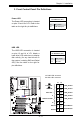
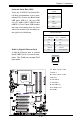
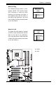
NIC1 LED Indicators
The NIC (Network Interface Control-
ler) LED connection for GLAN port1
is located on pins 11 and 12 of JF1.
Attach NIC LED cables to display
network activity. Refer to the table on
the right for pin denitions.
GLAN1 LED
PinDenitions(JF1)
Pin# Denition
11 Vcc
12 Ground
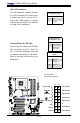
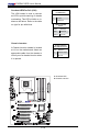
A. NIC1 LED
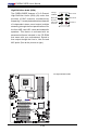
B. OH/Fan Fail LED
Overheat/Fan Fail LED (OH)
Connect an LED cable to the OH/Fan
Fail connection on pins 7 and 8 of
JF1 to provide advanced warnings
of chassis overheating or fan failure.
Refer to the table on the right for pin
denitions.
OH/Fan Fail LED
PinDenitions(JF1)
Pin# Denition
7 LED_Anode+
8 OH/Fan Fail
LED Signal
OH/Fan Fail Indicator
Status
State Denition
Off Normal
On Overheat
Flash-
ing
Fan Fail
B
A