
User`s manual

Chapter 2: Installation
2-13
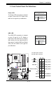
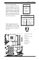
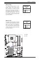
PowerButton
OH/Fan Fail LED
1
NIC1 LED
ResetButton
2
HDD LED
PowerLED
LED_Anode+
LED_Anode+
LED_Anode+
LED_Anode+
Ground
Ground
X
X
LED_Anode+
1516
X
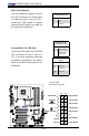
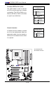
Power Button
The Power Button connection is located
on pins 1 and 2 of JF1. Momentarily con-
tacting both pins will power on/off the sys-
tem. This button can also be congured
to function as a suspend button (with a
setting in the BIOS - see Chapter 4). To
turn off the power when set to suspend
mode, press the button for at least 4
seconds. Refer to the table on the right
for pin denitions.
Note: Do not close or short Pins 1
& 2 since this will cause the system
to continuously reboot.
Power Button
PinDenitions(JF1)
Pin# Denition
1 Signal
2 +3V Standby
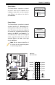
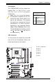
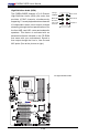
Reset Button
The Reset Button connection is located
on pins 3 and 4 of JF1. Attach it to a
hardware reset switch on the computer
case. Refer to the table on the right for
pin denitions.
Reset Button
PinDenitions(JF1)
Pin# Denition
3 Reset
4 Ground
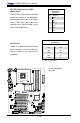
A. Reset
B. PWR Button
A
B
JL1
JI2C1
JI2C2
JOH
JPUSB1
JPI1
JWD
JPL1
JPAC
JLED
JPD1
COM1
JPW1
Floopy
JPW2
JWOL
DIMM1
DIMM2
CD1
SPKR1
LE1
JD1
Fan5
Fan4
Fan1
Fan3
Fan2
LAN1
JPUSB2
DIMM2B
DIMM4
DIMM3
USB 10/11
USB 8/9
USB6
1394_2
Slot7 PCI-E x1
Slot6 PCI-E Gen2 x16
Slot3 PCI 33MHz
HD AUDIO
JWOR
CPU
CPU Fan
FP Audio
1394_1
CMOS CLEAR
C2SEA/C2SEE
IDE
VGA
HDMI
USB/0/1
I-SATA3
I-SATA2
I-SATA1
I-SATA0
Slot1 PCI 33MHz
Slot5 PCI 33MHZ
Slot4 PCI-E x4 on x16
KB/Mouse
SPI BIOS
Slot2 PCI 33MHz
DIMM2A
DIMM1B
DIMM1A
USB7
JF1
USB2/3/4/5
SPDIF_Out
Printer
I-SATA4
I-SATA5
Battery
Intel
G45 (C2SEA)
G43 (C2SEE)
ICH10
Intel
Lan
CTRL
S I/O
IDE
CTRL