X2000 Gas Grill - LP X2000 USE AND CARE MANUAL FOR OUTDOOR USE ONLY ALWAYS KEEP YOUR GRILL COVERED WHEN NOT IN USE BEFORE YOU BEGIN – We’ve included easy-to-follow, step-by-step instructions which have been carefully written to ensure quick assembly of your grill. Reading the instructions will be a time saver in the end. YOU WILL NEED – A Phillips screwdriver, adjustable wrench, 1/2” wrench or socket and a 1/4” nut driver or socket will be needed to assemble this grill.
IMPORTANT SAFETY INFORMATION - Read this manual carefully before using your grill to reduce the risk of fire, burn hazard or other injury. - Extreme care should be used because of the high temperatures produced by this appliance. CHILDREN SHOULD NOT BE LEFT UNATTENDED IN AN AREA WHERE THE GRILL IS BEING OPERATED. - This appliance must be kept clear from combustible materials, gasoline or other flammable vapors and liquids.
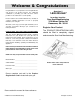
WelcomeAssembly & Congratulations Questions? Congratulations on your purchase of a new grill! We are very proud of our product and we are completely committed to providing you with the best service possible. Your satisfaction is our #1 priority. 1-800-229-5647 for written inquiries: Sure Heat Manufacturing 3130 Moon Station Rd Kennesaw, GA 30144 Please read this Use & Care Manual very carefully. It contains valuable information on how to properly maintain your new grill.
General Safety Instructions Do not use the rotisserie in the rain. NOTE: Do Not operate the main burners and infrared back burner at the same time. This can cause warping of the roll top grill hood. Electrical Grounding Instructions This appliance (rotisserie motor) is equipped with a three-prong (grounding) plug for your protection against shock hazard and should be plugged directly into a properly grounded three-prong receptacle. Do not cut or remove the grounding prong from this plug.
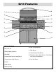
Grill Features 1 8 3 10 2 9 11 4 12 5 6 13 7 14 1. Roll Top Grill Hood 10. Rear Infrared Burner 2. Rotisserie Kit 11. Side Burner 3. Grilling/Cooking Surface 12. Control Knob: Side Burner 4. Side Shelf 13. Electronic Igniter: Main Burners, Side Burner and Rear Infrared Burner 5. Control Knob: Rear Infrared Burner 6. Control Knobs: Main Burners 14. Cart with Doors 7. Drawer 8. Hood Handle 9.
Getting Started 6
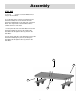
Assembly STEP ONE a. Use (2) Screws secure the Rubber Door Stop on the Cart Base. b. Set the Cart base on the floor and then lay the Caster Assembly Left on the left side and the Caster Assembly Right on the right side of the Cart Base. The angled side of the Cart Base will be towards the front of the base. c. Pick up the left side of the Cart Base and set the Caster Assembly Left in place by inserting the attached bolts through the three (3) holes in the Cart Base. d.
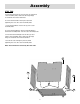
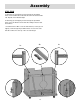
Assembly STEP TWO a. Place the Cart Side Left onto the two (2) outer fixed caster assembly bolts, make sure the large flange is toward the front of the Cart Base. b. Secure the Cart Side Leftt in place by hand tightening nuts onto the caster assembly bolts. c. Place the Cart Back onto the two (2) rear caster assembly bolts. d. Secure the Cart Back in place by hand tightening the Caster Assembly Nuts onto the caster assembly bolts. e.
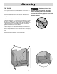
Assembly STEP THREE a. Press the cart sides back together making sure that the cart side flanges cover the cart back flange. b. Attach three (3) self tapping screws through the pre-drilled holes on the Cart Side Left into the cart back. Repeat for Cart Side Right. c. Tighten all six (6) caster assembly nuts with a wrench. The Spare L.P. Gas Tank Barrier must be installed to prevent storage of spare L.P. Gas Tanks.
Assembly STEP FOUR a. Attaching (2) Self Tapping Screws through the pre-drilled holes on the Left Bracket for the Cart Door Pin into the Cart Side Left. Repeat on the Bracket Right. b. Attaching (4) Self Tapping Screws through the pre-drilled holes on the two Bracket for the Cart Door Magnet into the Cart Cross Brace. c. Install Cart Cross Brace onto the Cart Sides by secure (2) self tapping screws though the pre drilled holes on each end of the Cart Cross Brace into the top of the cart side flanges.
STEP FIVE Assembly a. Use (2) self tapping screws to install the left drip pan guide in position. Note: The end with flange facing inside of the grill. b. Repeat step 5a to install the right drip pan guide. c. Use (6) screws to install the drawer guides in position. Noto: The end connected with the cross bar facing inside of the grill.
STEP SIX Assembly a. Loosen the four (4) grill mounting bolts so that there is approximately 1/4” between the bolt head and grill bottom. b. Have someone help you pick up the grill and set it squarely on top of the cart. c. Make sure the four (4) bolts fall through the large opening on the “ key hole” slots in the cart sides. d. Slide the grill forward in the “ key hole” slots until the front grill flange rests against the cart side flanges.
STEP SEVEN Assembly a. Remove the screws from three handles. b. Use (2) screws removed in step 7a to attach the handle onto the cart door. c. Repeat step 7b to install the handle to the other door. d. Use (2) screws removed in step 7a to attach the handle onto the front face of the drawer. e. Use (5) self tapping screws to attach the drawer tray to the drawer front face.
STEP EIGHT Assembly a. Place a piece of Styrofoam from the packaging inside the roll top grill hood to leave the hood propped open slightly. b. Attach the left shelf by inserting the two shelf hooks into the slots on the left side of the grill front face. c. After inserting the two shelf hooks, press the shelf against the grill and press downward until the shelf locks in place. Make sure the top trim strip is hanging all the way inside of the grill before pressing downward. d.
STEP NINE Assembly a. Place a piece of Styrofoam from the packaging inside the roll top grill hood to leave the hood propped open slightly. b. Attach the Right Shelf by inserting the two shelf hooks into the slots on the right side of the grill front face. c. After inserting the two shelf hooks, press the shelf against the grill and press downward until the shelf locks in place. Make sure the top trim strip is hanging all the way inside of the grill before pressing downward. d.
STEP TEN Assembly a. Remove two screws from the burner valve assembly. b. Carefully insert the valve assembly into the cast burner. You will need to angle the tube into the burner assembly. Make certain that the hose is pointing down when the valve is put in place. Then push the valve stem out through the opening in the front of the side burner shelf assembly, lining up the holes on the valve assembly with the openings on the burner shelf. c.
STEP ELEVEN Assembly a. Place the electronic igniter button into the igniter hole on the front left of the side burner shelf. b. Secure the igniter in place using the plastic lock nut. Make sure to tighten securely. c. Install AA battery, negative side first. d. Install spring and cap assembly and tighten securely. e. Attach the two igniter wires to the igniter button and igniter module. Note: Make sure you follow the left picture to attach them. f.
STEP TWELVE Assembly a. Center the brass burner cap on top of the side burner head. b. Place the side burner grate on to the side burner tray.
STEP THIRTEEN Assembly a. Place right hand door on an angle over the right side door pivot. b. Tilt the top of the door toward the grill, while depressing the door pivot pin on the bracket. c. Move the door slightly until the pin locks into place in the hole on the top of the Cart Door Right. d. Repeat steps 13a - 13c for left door installation.
STEP FOURTEEN Assembly a. Slide the drawer assembled in step 7d - 7e into the drawer guides under the front face. Make sure the little wheels on the side of the drawer move on the drawer guides. b. Slide drip pan in place through the hole on the cart back.
Assembly STEP FIFTEEN a. Insert the flavor grids into the cutouts with triangle ridges facing up. b. Install main cooking grates on the ledges provided on the grill to create your cooking surface. c. Attach rear igniter shield using two (2) self tapping screws. d. Rest bread warming grate on four (4) slots above cooking grid. The finished grill should look like the photo on the cover of this Use and Care Manual.
Gas Requirements L.P. GAS INSTALLATION Cascade™Gas Grills that are set to operate with L.P. gas come with a high capacity hose and regulator assembly. (Note: Only use the pressure regulator and hose assembly supplied with the grill or a replacement pressure regulator and hose assemblies specified by Cascade™). This assembly is designed to connect directly to a standard 20 lb. L.P. cylinder. L.P. Cylinders are not included with the grill. L.P. Cylinders can be purchased separately at an independent dealer.
Pre Operation Leak Testing GENERAL INFORMATION Although all internal gas connections on the grill are leak tested prior to shipment, a complete gas tightness check must be performed at the installation site due to possible shifting during shipment, installation or excessive pressure unknowingly being applied to the unit. Periodically check the whole system for leaks and immediately check the system if the smell of gas is detected. BEFORE TESTING Do not smoke while leak testing.
BEFORE LIGHTING Lighting the Grill burner between the flavor grids. Position the match near the burner ports and push and turn the control knob counter clockwise to the “ HIGH” position. (See Fig. 2 - 3) Important! Before Lighting: • Check the gas supply line for cuts, wear or abrasion. Note: If the grill will not light after several attempts see the trouble-shooting section of this manual. Turn the control knobs to the OFF position when not in use.
GRILL LOCATION Using the Grill Do not use the grill in garages, breezeways, sheds or any enclosed area. Never operate the grill in enclosed areas as this could lead to a carbon monoxide buildup, which could result in injury or death. Place the grill on a level surface. Avoid moving the grill while it is operation. NOTE: The grill will operate best if it is not facing directly into the wind.
Using the Rotisserie The grill rotisserie system is designed to cook items from the back using infrared heat. The rotisserie burner is an infrared type which provides intense searing radiant heat. Preferred by chefs over other cooking methods, this intense heat sears in the natural juices and nutrients found in quality cuts of meats. Remove the warming rack from the grill when using the rotisserie to prevent warping from the intense heat of the infrared unit.
Accessory Lighting ROTISSERIE LIGHTING Open the lid. Push and turn the control knob for the rotisserie counter clockwise to the “ HIGH” position. Wait 5 seconds. Then press and hold the electronic igniter button. You’ ll hear a snapping sound. If the burner does not light in 4 seconds, turn the control knob to OFF and wait 5 minutes before trying again. Once lit, turn the control knob to the desired setting. (See Fig.
Care and Maitenance GENERAL MAINTENANCE - Keep outdoorcooking gas appliance area clear and free from combustible materials, gasoline and other flammable vapors and liquids. - Do not obstruct the flow of combustion and ventilation air. - Keep the ventialtion openings of the cylinder enclosure free and cleat from debris. - Visually check the burners. DRIP TRAY Normal: soft blue flame Out of Adjustment: Hard blue flames- too much air Poor Combustion: Wavy, yellow flames-too little air.
Troubleshooting Your Grill GENERAL TROUBLE SHOOTING You should inspect the burners at least once a year or immediately if any of the following conditions occur: • The smell of gas. • Flames appearing mostly yellow. (some yellow at the tips is OK) • The grill will not get hot enough. • Burners make a snapping noise. • The grill heats unevenly. SPIDER AND INSECT WARNING Spider and insects can nest in the burners of this or any other grill and cause the gas to flow from the front of the burner.
PROBLEM Troubleshooting Your Grill SOLUTION Grill will not light with a match or low heat with dial set to "High" position. • Is your gas supply fully turned on? • If this is an L.P. grill is there gas in your tank ? Check your gas level. • If this is an L.P. grill, shut off gas supply, disconnect gas line at tank, reconnect the line to the tank. • Make sure all the knobs are in the off position, then open the gas supply valve on the L.P.
Warranty 31