
Manual

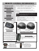

BURNER SYSTEM LOCATION
1. TheBurnerSystemshouldbelocatedtowardsthebackandcenteredinthecombustionchamber
oftheventedreplace.TheBurnerSystemshouldbecenteredfromlefttoright,withaboutan
inch of space on either side.
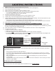
CONNECTING GAS SUPPLY TO BURNER PAN AND LOG GRATE PLACEMENT
1. Place Burner System in proper location.
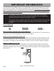
2. Attach3/8”to1/2”gasinletttingtothe1/2”gas
supplystub.(See Figure 2)
3. Carefullybendthearedtubingasneededtomake
theconnectionbetweentheburnerassembly
andthegasinlettting.
4. Nextattachthearedtubingtotheburnerassembly
rst,thentothegasinlettting.
- Avoidkinkingthearedtubingwhilebending.
Iftubingmustbecut,useatubecutter.Flare
thecutendofthetubewithaaringtube.
5. Becertainallconnectionsaretightandusepipecompoundonallmalethreadstosealjoints.
NOTE:ThepipecompoundmustberesistanttotheactionofL.P.gas.Testallconnectionswith
asoapywatersolutionwithgassupplyturnedon.Ifbubblesappearonanyconnection,retighten
andreset.Onceitisdeterminedtherearenoleakswhatsoever,turnoffgassupplyandmoveto
nextassemblystep.
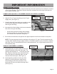
GRANULE AND EMBER PLACEMENT
A. Spread granules over the installed burner pan.
Granulesshouldnotlluptheentirepan.The
granules should stop 3/4” - 1” from the top of the
pan.SlopetheGranulesdowntowardthefront
ofthepanwithoutoverowingthemoverthe
frontlipoftheburnerpan.(See Figure 3)
B. Spreadglowingembersoverthetopofthe
granules,coveringtheentiresurfacearea,
concentrating on the front and sides of the
burner pan for the most realistic burning effect.
(See Figure 3)
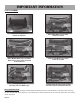
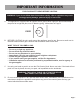
IMPORTANT INFORMATION
Gas Supply
Stub
Gas Inlet
Fitting
Flared
Tubing
Figure 2
Figure 3
Glowing
Embers
Granules
Page 5