
Instructions / Assembly

2
COOPER LIGHTING SOLUTIONS IB50533821 Installation instructions
Installation Instructions–Sure-Lites APELMINI
Wall Mount Installation
NOTE: Max Mounting Height is 17ft
Conduit Installation
1. Extend unswitched 24-hour AC supply of rated voltage
to junction box. Leave at least 8 inches of slack. Circuit
should not be energized at this time.
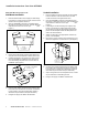
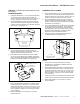
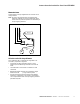
2. Open the APELMINI by inserting a screwdriver at the
two holes on the bottom of the unit. This will deflect the
snap features to allow the unit to open. (See
Figure 1)
1. Extend unswitched 24-hour AC supply of rated voltage
to device location. Leave at least 6 inches of slack.
Circuit should not be energized at this time.
2. Open the APELMINI by inserting a screwdriver at the
two holes on the bottom of the unit. This will deflect the
snap features to allow the unit to open. (See
Figure 1)
3. If mounting to conduit and using it as support, skip
to step 4. If mounting to surface and using conduit
as wire-way, knock out the appropriate mounting hole
pattern on the backplate. Mount the backplate to the
wall in the desired location.
4. Attach conduit hubs to the appropriate conduit entry
points on the backplate.
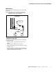
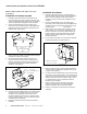
5. Remove the correct conduit cover knockout(s) for your
desired configuration of conduit access. (See Figure 3)
Conduit
knock-out
locations
Insert
screwdriver
to open
EZ-Hang hole
in housing
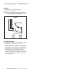
Tab on backplate
Figure 1.
Figure 2.
Figure 3.
3. Knock out the appropriate mounting hole pattern and
wire pass hole on the backplate to match junction box.
4. Install the backplate to the junction box using screws.
Once the backplate is installed the unit can be hung
from the EZ-Hang snap features to increase ease of
installation. (See Figure 2)
5. Connect power supply and ground in accordance with
local codes. Wire connections as follows: 277VAC line
to orange lead or 120V line to black lead; neutral to
white lead. Cap unused line lead (see Schematic).
6. Energize AC supply. Test Button will illuminate.
6. Connect power supply and ground in accordance with
local codes. Wire connections as follows: 277VAC line
to orange lead or 120VAC line to black lead; neutral to
white lead. Cap unused line lead (see Schematic).
7. Snap housing back onto the backplate. Ensure no wires
are pinched while re-assembling the unit.
8. Energize AC supply. Test Button will illuminate.