
Instructions / Assembly
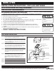

WALL MOUNT INSTALLATION
Step 1. Extend unswitched 24 hour AC supply of rated voltage to
junction box (by others). Leave at least 18 inches of slack.
Circuit should not be energized at this time.
Step 2. Disassemble sign by removing the screw holding the side
cover and sliding the glass panel out. Remove power tray by
placing a screwdriver in the rectangular slot in the upper left
or right, and pulling down.
Step 3. Knock out the appropriate mounting pattern and wire pass
hole to match junction box. Insert bushing into wire access
hole to prevent abrasion on supply wires. Mount wire saddle
with peel off adhesive backing to prevent wires from
shadowing the EXIT face. Bring wires through back of fixture.
Step 4. Replace power tray into top of sign frame. Check to make
sure that power tray is held securely in place. Reconnect
battery and power supply leads to LED circuit board if
necessary.
Step 5. Connect power supply and ground in accordance with local
codes. Wire connections as follows: 277V line to Orange
lead or 120V line to Black lead; Neutral to white lead.
Ground to Green lead; Cap unused line lead.
Note: Connections must be in power tray or junction box.
Step 6. Mount to junction box.
Step 7. Energize AC supply, LED display will come on.
Step 8. Replace glass panel, side cover, and screw.
SURE-LITES
INSTALLATION INSTRUCTIONS – CHX L.E.D. EXIT SIGNS
For AC and Self Powered, Wall, Ceiling, and End Mount
IMPORTANT SAFEGUARDS
WHEN USING ELECTRICAL EQUIPMENT, BASIC SAFETY PRECAUTIONS SHOULD ALWAYS
BE OBSERVED INCLUDING THE FOLLOWING:
1. READ AND FOLLOW ALL SAFETY INSTRUCTIONS
2. Dry location only. Do not use outdoors.
3. Do not use in hazardous locations, or near gas or electric heaters.
4. Do not let power supply cords touch hot surfaces.
5. Use caution when servicing batteries. Battery acid can cause burns to skin and eyes. If acid is spilled
on skin or in eyes, flush acid with fresh water and contact a physician immediately.
6. Do not use this equipment for other than the intended use.
7. Installation is to be performed only by qualified personnel.
8. Install in accordance with National Electric Code and local regulatory agency requirements.
9. The use of accessory equipment not recommended by the manufacturer may cause an unsafe
condition.
10. Equipment should be mounted in locations and at heights where it will not readily be subjected to
tampering by unauthorized personnel.
11.
SAVE THESE INSTRUCTIONS
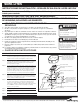
JUNCTION BOX (BY OTHERS)
NOTE:
W
hen using non-metallic
boxes, be sure to use the proper
b
racket for orientation of the
mounting screws similar to a 54151
box.
MOUNTING STRAP
JUNCTION BOX SCREWS
(BY OTHERS)
#8-32 X 3/8 MOUNTING SCREWS
CANOPY
BUSHING
POWER PACK
END SCREWS
#8-32 X 3/8 CANOPY
MOUNTING NUTS
BUSHING (WALL MOUNT)
SCREWS (BY OTHERS)
EXIT HOUSING
POWER PACK
STAR WASHERS
#8-32 X 1 MOUNTING SCREWS
Risk of Electric Shock
Disconnect power at fuse
or circuit breaker before
installing or servicing.
Risk of Fire/Electric
Shock
If not qualified, consult an
electrician.
Customer First Center 1121 Highway 74 South Peachtree City, GA 30269 770.486.4800 FAX 770.486.4801 10/22/10 049-209