
Instructions / Assembly

SURE-LITES
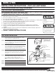
CEILING OR END MOUNT INSTALLATION
Step 1. Extend unswitched 24 hour AC supply of rated voltage to junction box (by others). Leave at least 18 inches of slack. Circuit should not be ener-
gized at this time.
Step 2. Disassemble sign by removing the screw holding the side cover and sliding the glass panel out. Remove power tray by placing a screwdriver in
the rectangular slot in the upper left or right, and pulling down. Relocate supply wires through power tray to nearest knockout if ceiling or end
mounting.
Step 3. Knock out the appropriate mounting pattern on top or side of exit sign to accommodate canopy.
S
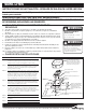
tep 4. Fasten Canopy to Exit Frame by means of two 8/32 screws, lock washers and nuts.
Step 5. Mount mounting strap to junction box by choosing proper slots and using screws supplied with junction box.
Step 6. Screw (2) 8- 32 X 1 round head machine screws into mounting strap.
Step 7. Feed wires through exit-canopy combination and fixture center of adapter plate.
Step 8. Connect power supply and ground in accordance with local codes. Wire connections as follows: 277V line to Orange lead or 120V line to Black
lead; Neutral to white lead. Ground to Green lead; Cap unused line lead. Note: Connections must be in power tray or junction box.
Step 9. Mount exit-canopy combination to adapter plate using (2) acorn nuts provided.
Step 10. When end mounting, route wires along top and side edges of exit frame and secure wires into adhesive wire saddle.
Step 11. Replace power tray into top of sign frame. Check to make sure that power tray is held securely in place. Reconnect battery and power supply
leads to LED circuit board if necessary.
Step 12. Replace glass panel, side cover, and screw.
Step 13. Energize AC supply, LED display will come on.
OPERATION 1. To test Self Powered units, depress test switch. LED Display will remain lit when switched to battery power.
2. Release test switch, LED Display will operate with AC supply.
MAINTENANCE: 1. Servicing of any parts should be performed by qualified personnel. For replacement parts see fixture label for proper
identification of catalog number.
2. Replace batteries every 8 to 10 years according to ambient. Equipment should be tested regularly in accordance with
local codes.
CAUTION: This equipment is furnished with a sophisticated low voltage battery dropout circuit to protect battery from
over discharge after its useful output has been used. Allow 24 hour recharge time after installation or power failure for full
load testing.
TROUBLE SHOOTING GUIDE
LEDs do not light in emergency mode – Charge indicator LED off before test.
• Check AC supply - be sure unit has 24 hour AC supply.
LEDs do not light in emergency mode – Charge indicator LED on before test.
• Either output shorted or over
loaded or battery not
connected.
• Battery discharged - permit
unit to charge for 24 hours and
then retest. If LED DISPLAY is
still off, check charger for
charge function. If functioning
properly, replace battery.
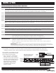
TEST
SWITCH
CHARGE
INDICATOR
BATTERY
PACK
POWER
SUPPLY
NOTE: BATTERY, CHARGE
INDICATOR, AND TEST
SWITCH NOT INCLUDED ON
AC ONLY MODELS
LED BOARD
WHITE LEAD - TO NEUTRAL
BLACK LEAD - TO 120V
ORANGE LEAD - TO 277V
Customer First Center 1121 Highway 74 South Peachtree City, GA 30269 770.486.4800 FAX 770.486.4801 10/22/10 049-209