
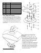
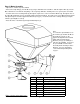
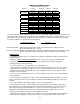
Replacement Part List


5
Item # Part # Description
1 N/A Snap Ring (Included w/ Motor)
2 10118 Disc - Spinner
3 12564 Nut - Nyloc, 10-32
4 10114* Bracket - Motor Support, Lower
5 19913 Motor - Spreader, 12V
6 10197 Bolt - Carriage 5/16-18 X 1
7 AS021 Tie, Black 5 1/2"
8 10117* Shield - Spreader
9 3844 Knob - T, 5/16-18
When ordering replacement parts
*USE PAINT CODE: TK=BLACK
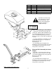
Step 3: Motor Assembly
• Tip: Items 3, 4 and 5 are preassembled.
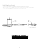
• Remove the Snap Ring (1) from the Motor (5) using a small flat head screwdriver. Slide the Spinner Disc (2) onto the
Motor Shaft and secure with the Snap Ring. If the snap ring is difficult to install by hand, use a pair of pliers to install it.
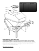
• Insert the 5/16-18 X 1” Carriage Bolts (6) through the square holes of the Lower Motor Bracket (4), through the slots of
the Upper Motor Bracket (2 on pg 4) and through the Spreader Shield (8). The guide on the Lower Motor Bracket (4) will
slide up through the slot in the Upper Motor Bracket (2 on pg 4) . Fasten the 5/16-18 X 1” Carriage Bolts (6) using the
T-Knobs (9) and tighten securely.
• Route the wires of the Motor (5) through the Black Zip Tie (7).
Note:
To control the spread width, loosen
the T-Knobs (9) and slide the Motor
Assembly up or down. In the
uppermost adjustment the material
will be deflected down by the
Deflector (8 on pg 4) resulting in a
narrower spread width. To increase
the spread width, slide the Motor
Assembly down and away from the
Deflector. For more information,
see the Material Spreading Chart
on pg 11.