
Product Manual
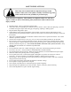
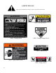
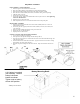


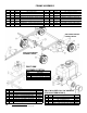
Table Of Contents
- Cover
- Warranty
- Safety Precautions
- Safety Decals
- Required Assembly
- Operation 1
- Operation 2
- Operation 3
- Maintenance
- Frame Detail
- Gas Tank Detail
- Blade Driver Detail
- Deck Detail
- Grass Chute Detail
- Caster Detail
- Motor Base Detail
- Engage Lever Detail
- Height Adjust Handle Detail
- Safety Switch Detail
- Idler Detail
- Belt Configuration
- Ordering Information

5
*Battery cover not shown
Battery Mounting Detail
A U1 battery is required
(not included). Position
battery hold down
bracket as shown.
Tighten nuts so battery
will not shift position.
REQUIRED ASSEMBLY
FRONT WHEEL CASTER ASSEMBLY
1. Remove single nut and washers from caster shaft.
2. Place one washer (NB195) on the shaft of the caster/wheel subassembly.
3. Slide same shaft through the bearing/frame with wheel towards the ground.
4. Place the other washer (NB195) on the shaft; it should be resting on the top bearing.
5. Add thin washer (17x195).
6. Thread nyloc jam nut onto shaft.
7. Tighten nut snuggly, making sure shaft threads enter the nyloc of the nut. Over-
tightening
of this nut will bind caster.
8. Repeat process for other front side.
9. Push on plastic dust covers over nut and thin washer until it snaps into place.
REAR WHEEL ASSEMBLY
1. Remove cotter pin from axle and remove thin washer (NB149) from axle. Leave two
NB178 washers on axle.
2. If necessary (to take up space) slide extra washer (NB178) over axle, then wheel (with
valve stem out).
3. Slide on washer (NB149) and replace cotter pin in end of axle.
4. Bend cotter pin so it will not fall out.
5. Repeat process for other wheel.
OFFSET & CENTER TOW HITCH BAR ASSEMBLY
1. Lay out parts according to the diagram.
2. Insert part 661A into part 662 and pin with the hitch pin (H11).
3.
Insert part 661 into part 661A. Choose from the 3 holes to set the desired hitch length. Pin
with a hitch pin (H11).
4. Part 662 slides into the front tube of the frame. Again, choose from the 3 holes to arrange
desired offset. Pin with a hitch pin (H11).
5. Eliminate step 2 for hitching from the center bracket. Only one method can be used at a
time.