
Universal Trail Mower Owner's Manual


REQUIRED ASSEMBLY
FRONT WHEEL CASTER ASSEMBLY
1. Remove single nut and washers from caster shaft.
2. Place one washer on the shaft of the caster/wheel sub-assembly.
3. Slide same shaft through the bearing/frame with wheel towards the ground.
4. Place the other washer on the shaft; it should be resting on the top bearing.
5. Thread nyloc jam nut onto shaft.
6. Tighten nut snuggly, making sure shaft threads enter the nyloc of the nut.
Over-
tightening of this nut will bind caster.
7. Repeat process for other front side.
REAR WHEEL ASSEMBLY
1. Remove cotter pin from axle.
2. Slide washer [ NB149 ] if necessary and wheel[ valve stem out] onto axle and replace
cotter pin.
3. Bend cotter pin so it will not fall out.
4. Repeat process for other wheel.
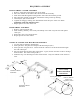
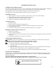
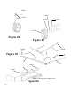
OFFSET & CENTER TOW HITCH BAR ASSEMBLY
1. Lay out parts according to the diagram.
2. Insert part 661A into part 662 and pin with the hitch pin (H11).
3. Insert part 661 into part 661A. Choose from the 3 holes to set the desired hitch length.
Pin with a hitch pin.
4. Part 662 slides into the front tube o
f the frame. Again, choose from the 3 holes to arrange
desired offset. Pin with a hitch pin (H11).
5. Eliminate step 3 for hitching from the center bracket. Only one method can be used at a
time.
5
CENTER TOWING
POSITION
OFFSET TOWING
POSITION
Bent Pin, Hair Pin
and Receiver
supplied by others.
Existing Rear Hitch.
ATV or Utility
Vehicle Attachment
Instructions
6
6
1
6
6
1
A
6
6
2
H11